Best Of
Re: Filtering query() in HyperView Python API
Thank you for your answer, those methods solved my problem.
Regards,
Daniele
Re: Element size?
Hello,
You can do this using TCL.
First open the command Window
Go to View>>Command Window
Then type the following code:
*createmark elems 1 displayed
hm_getaverageelemsize 1
This will give you the average element size.
credits @tinh
Thankyou
Hey Sanjay,
Can you tell me what this value refers to, in case of triangular elements?
And do you know how to calculate the average element size of 3D tetra elements?
Thank you!
Re: Replaced mixer blades not rotating in HyperStudy-driven EDEM simulation
Hi @kyle66,
I am adding my comments from HyperStudy point of view to give an understanding of the process involved when HyperStudy is integrated with a solver.
HyperStudy will only execute EDEM (or any other solver) solver file as is & does not have default means/provisions to modify the solver file.
Hence, to merge the geometry components, it needs to be specified in the EDEM solver deck itself beforehand. However, I am not sure if it can be done in EDEM & hence, would like @Stephen Cole to comment on the same.
Many thanks.
Kind Regards
Garima Singh
Engineering Data Science
Re: Failed Activation on Linux - Looking for a Private Support Contact
@juanpsm Thanks for reporting this issue. I will escalate it to the correct team.
 Jocelyn
Feko: Reciprocal Excitation solution configuration – CADFEKO and POSTFEKO workflow
Overview
The antenna reciprocity theorem [1] relates the antenna load current for given plane wave excitation to the radiation pattern when the antenna is excited. The antenna is assumed to be made of linear and reciprocal components.
With the CADFEKO Reciprocal Excitation solution configuration, the antenna load response under plane wave excitation can be computed as a post-processing step in POSTFEKO.
Using this workflow reduces computationally effort as only the antenna under a single excitation needs to be solved. For example, modelling a direction-finding antenna array with multiple plane wave incidence angles reduces the number of solutions to the number of antennas in the array times the number of frequencies. In post-processing the user can specify the plane wave properties like amplitude, polarisation, polarisation angle and ellipticity. The incident plane wave directions will either coincide with the discrete samples of the requested far field pattern or could be specified when a continuous far field request is available.
This workflow also allows calculation of induced currents and voltages of cable harness loads, with plane wave excitation and Schematic link connections. Schematic link connections are only supported for radiating cable harnesses.
CADFEKO solution setup
New Reciprocal Excitation configuration
Figure 1: Reciprocal Excitation solution configuration
Two parts of the Reciprocal Excitation configuration:
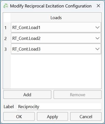
1) Define loads where induced current with plane wave excitation is required.
Figure 2: Example of Reciprocal Excitation dialog
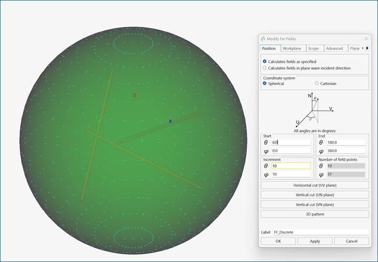
2) Add far field request(s). Two options: discrete far field sampling or continuous far field. First choice would be to request a continuous far field as then the user can specify arbitrary plane wave incident directions as part of the POSTFEKO post processing step. However, the continuous far field request is not supported or efficient for all solution options, like real ground planes and electrically large structures. In these cases, it is recommended to request a far field with discrete sampling, and the plane wave incident directions will be limited to the discrete sampling of the far field.
Figure 3: Example of far field request
POSTFEKO post-processing
1) Load the solved model containing a Reciprocal Excitation configuration
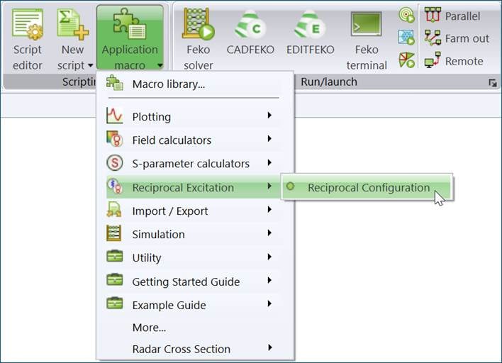
2) Run the Reciprocal Configuration application macro.
Figure 4: Reciprocal Excitation post processing application macro
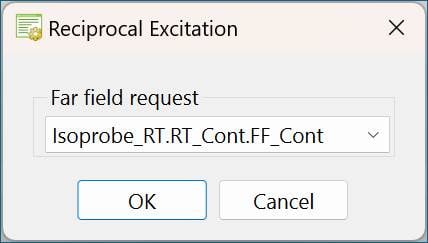
3) Select a far field associated with a Reciprocal Excitation configuration
Figure 5: Dialog to select far field request associated with Reciprocal Excitation configuration
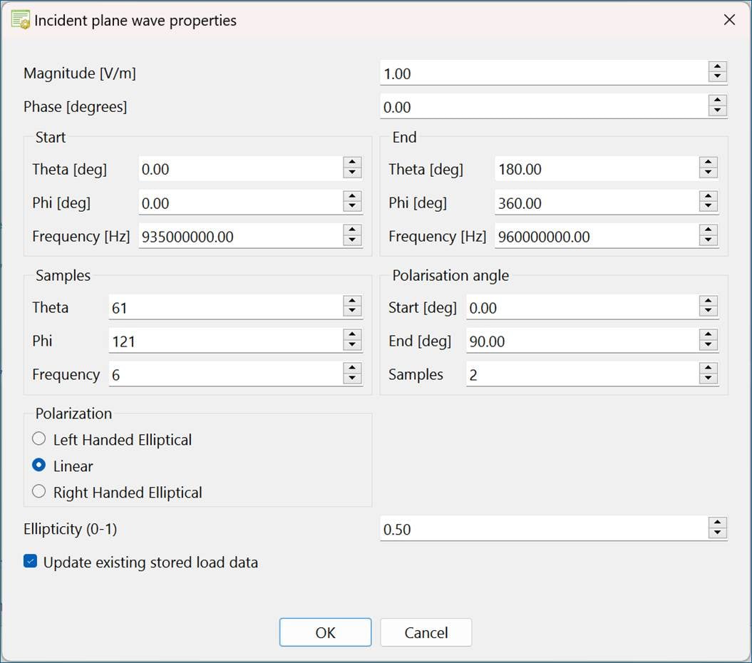
4) Specify solution properties: Frequency solution and plane wave properties
Figure 6: Dialog to set frequency and plane wave solution properties when both continuous frequency solution and continuous far field request are selected
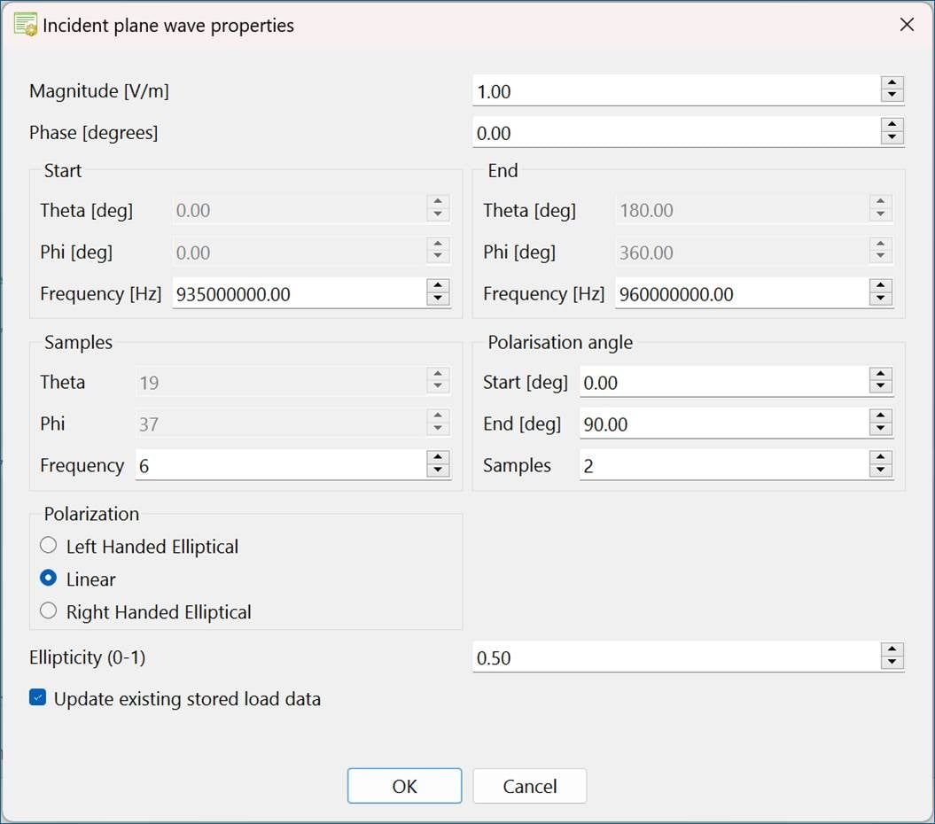
For both continuous frequency and a continuous far field request all parts of the dialog are active, see Figure 6. For continuous frequency and a discrete far field request the plane wave incident angles are greyed out (can’t be changed), see Figure 7.
Figure 7: Dialog to set frequency solution properties with continuous frequency solution and discrete far field request are selected
5) OK to run the application macro
6) The induced load data is stored with the same label as specified for the Reciprocal Excitation configuration, see Figure 2. Hovering the mouse pointer over the stored data item listed in the Project browser will provide more information associated with the induced load data, see Figure 8.
Figure 8: Stored data note
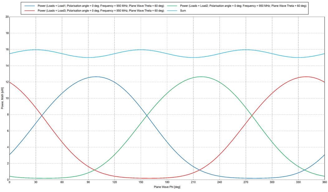
7) The stored data has 5 axes: Loads, Polarisation, Frequency, Plane Wave Theta and Plane Wave Phi and can be plotted on Cartesian graphs and Cartesian Surface graphs. The normal load quantities are available: Current, Voltage, Impedance and Power, see Figure 9 for example of load power vs incident plane wave phi angle.
Figure 9: Example of load power versus plane wave phi
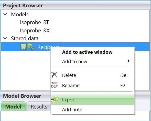
8) The stored data can be exported to file via the Project browser
Figure 10: Export stored load data
[1] R.H. Clarke and John Brown, Diffraction Theory and Antennas, Ellis Horwood Series in Electrical and Electronic Engineering, 1980.
Re: Hyperstudy Installation
Hi @JT_Wijnker_11,
Our Licensing & Installation support team had provided initial suggestions on the Case CS0801379 on 23rd October.
Kindly respond to the same case so that the support team can help accordingly.
Many thanks.
Kind Regards
Garima Singh
📅September Community Roundup
Hi Everyone,
While this roundup arrives a bit later than planned, we wanted to ensure that we captured the key highlights and achievements from September. Lets dive in.
📢Altair RISE Updates
As you know our RISE Program(Recognition for Innovation, Solutions & Expertise) officially launched in August. This exclusive recognition program celebrates our most engaged community contributors with amazing rewards, exclusive access and well deserved recognition for their expertise. Learn more about RISE here
We are still accepting nominations for RISE. If you would like to join the RISE program, email us your nomination at community@altair.com
Welcome @Hakan_20716 @Mugundhan03 to our RISE program!
We're also thrilled to announce that @Philip_Holland has received the Altair Explorer Badge, congratulations on another milestone!
🏆September Leaderboard
Our community champion for September is Dr. César Pérez🥇
@Caperez is an industrial engineer and scientist whose career bridges higher education, research, and business leadership. His work spans complex dynamic systems, materials science, data analysis, and decision-making for both research and enterprise contexts. Learn more about him here.
Here's our top ten members in September:
Thank you so much for participating and being part of our community!
- @Philip_Holland
- @Luca Cavagna
- @Roger DeAngelis_21630
- @willyh
- @Q.NGUYEN-DAI
- @Enzo
- @Juansmz_
- @Nithin_
- @Vishakha Pandharpure_20595
- @mss15m
⭐️ Featured Posts and Exchange Projects
- EDEM API - Collision Metrics by @Renan
- PhysicsAI Tips and Tricks 1 : Enabling GPU for PhysicsAI 2025.1 version on Linux by @Garima_Singh
- Modeling of Hypervelocity Impact in Composite Laminates with Altair Radioss by @PierreChristophe_Altair
- Altair Personal SLC constrained Linear Regression to reduce penalty by @Roger DeAngelis_21630
- Buckling Studies of a Short-Span Steel Girder Bridge by @Matthew_Sauer1
Did you know you can share your projects/templates with the Altair Community? Get Started here.
📆 Coming up Next
- ATCx Digital Twin – From Idea to Reality 2025 - October 23
- Simulating large models in Feko and enhancements to MLFMM solver - October 23
- ATCx Unlocking Data Science & AI 2025 - November 5
View all events here.
💁♀️ Can you help?
Calling all problem-solvers and subject matter experts! We have several questions still looking for answers and we'd appreciate your help!
Take a moment to check out what fellow members are asking and share your knowledge with our community.
Until next time
Thank you for being an integral part of the Altair Community. If you have any questions or feedback, please don't hesitate to reach out to us at community@altair.com
 Jocelyn
Re: Student Edition License problem
HI,
Can you confirm you have downloaded and installed OptiStruct (mechanical solvers)
And HyperMesh
You need to Install HM (desktop exe) and OptiStruct (Mechanical Solvers exe) to the same installation folder
HM (Desktop exe) consists of - HyperMesh, HyperView, HyperStudy, MotionView etc.
OptiStruct (Mechanical Solvers exe) consists of - OptiStruct, RADIOSS, Multi Scale Designer, MotionSolve, etc.
 Rahul_P1
Re: Student Account Blocked
Please do not enter your Altair One Credentials in the RapidMiner Login window of AI Studio,
To Activate AI Studio, (previously called RapidMiner Studio), when using the Altair Student Edition via Altair One1) Follow the instructions in the blog titled - Steps to Activate AI Studio with the Altair Student Edition License Key from Altair One.com in Windows and other related AI Studio Troubleshooting - Steps to Activate AI Studio with the Altair Student Edition License Key from Altair One.com in Windows and other related AI Studio Troubleshooting — Altair Community
2) Follow the instructions in the blog titled if using MAC OS- Steps to Activate AI Studio with the Altair Student Edition License Key from Altair One.com in MAC OS (apple) and other related AI Studio Troubleshooting –
You can alternatively follow video instructions here -
 Rahul_P1
Re: How to determine the K coefficient in the Impact and Bistop functions?
Dear @Christopher_Fadanelli
I got it
Thank u very much!!!


