Introduction
We will simulate the WLTP Class 3b drive cycle of 1,800sec in just 25sec of simulation time, which is x72 times faster than real time. Let's see how!
The first part of this workflow is already covered here:
Faster-than-Real-Time EV Drive Cycle Simulations with PSIM-trained Fit Models | Part1
The second part will cover the creation of the Speed Profile for the drive cycle, Road Load modeling, Regenerative Braking strategy, and finally, the complete System Integration.
Let's get started!
Speed Profile | WLTP Class 3b
For this example, we will utilize the WLTP Class 3b dataset found in this page:
Worldwide Harmonised Light Vehicles Test Procedure
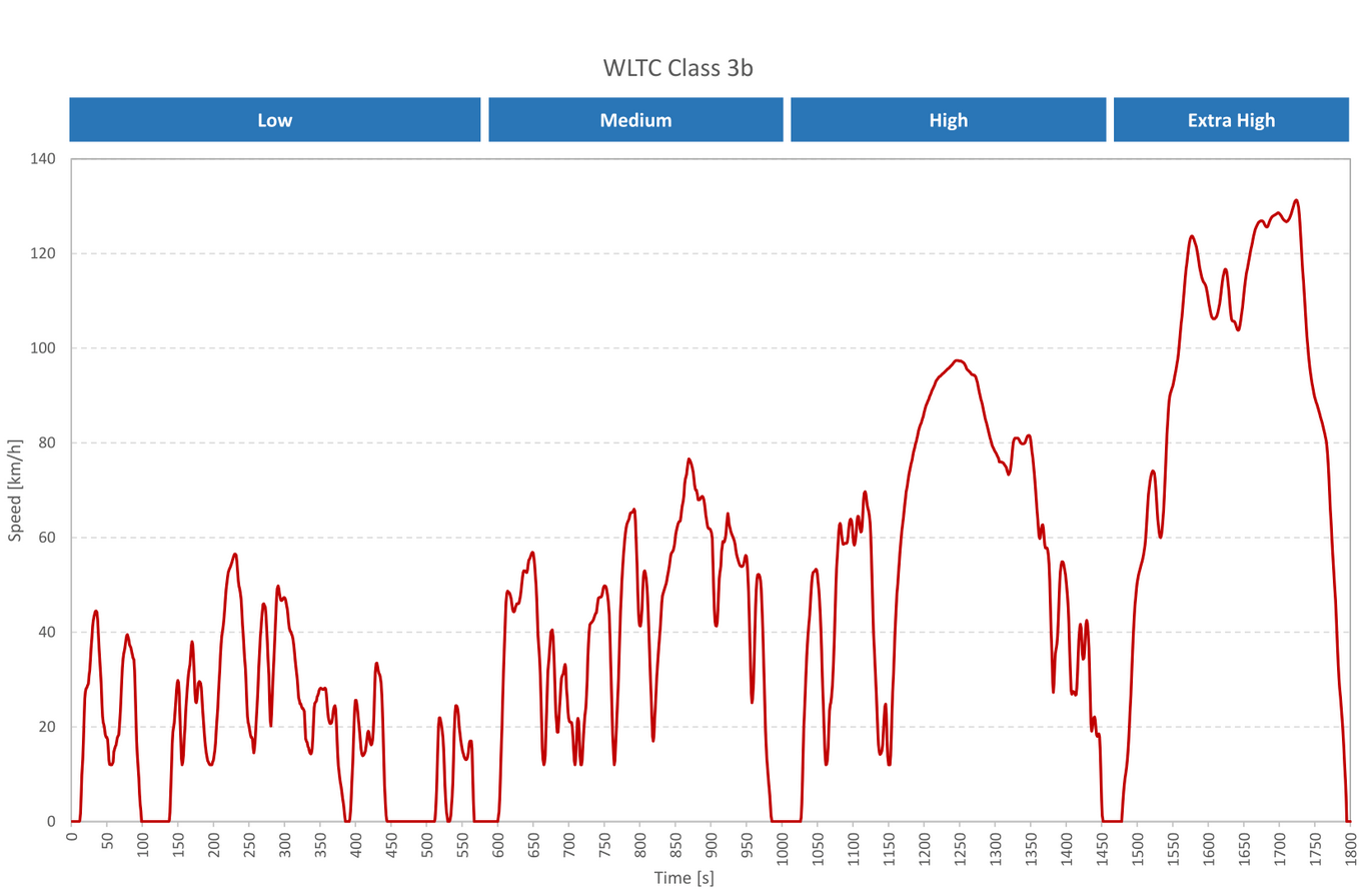
The dataset was digitized using a digitizer tool and saved as a .csv file. Then, the column headers were added: 'Time' for Column 1 and 'Speed_kph' for Column 2.
Please keep in mind that this is just an approximation of the WLTP cycle. Digitized from an image. Please refer to original WLTP data for your own projects.
The final dataset can be found here:
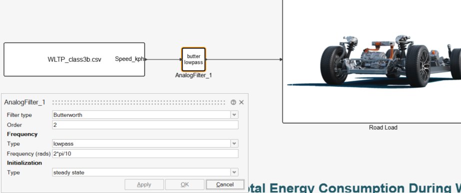
Twin Activate's "From CSV"block can interpolate between data points, so constant sampling intervals are not necessary. We can use a fixed time step in the simulation along with a filter in this case to smooth the imperfections of our WLTP graph digitizing process. A Butterworth 2nd order filter was used with Lowpass cutoff [2*pi/10 rad/s] and "steady state" initialization type.
* Feel free to use your own speed profile. You can work with your own drive cycles or track data. This example is particularly useful for Formula Student teams aiming to calculate the required energy for the "Endurance Event" of the Formula Student competition.
Road Load | Tractive Force Calculation
So far, we've built system-level fit models that can predict outputs such as inverter losses, motor losses, system efficiency, and semiconductor cost based on design inputs such as:
- Semiconductor selection
- Gate resistance
- Inverter case temperature
- Motor shaft speed & torque
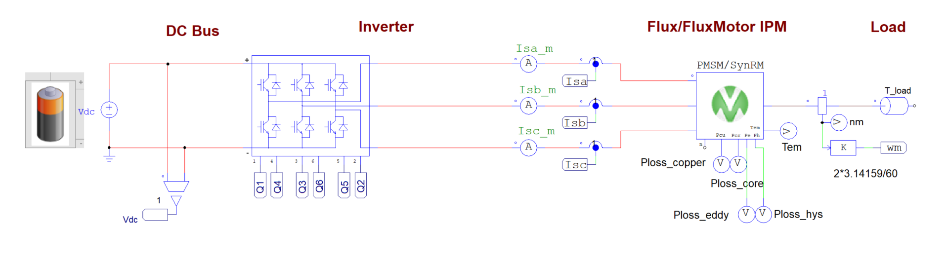
The outputs we get are based on Regression or Neural Network fit models - trained with PSIM data. This means that they will inlcude high fidelity effects such as switching losses and pwm motor losses without actually solving a switching simulation.
We now need to provide the fit models with the motor shaft speed and torque.
- Speed to RPM:
Convert vehicle speed (WLTP Class 3b) to motor RPM using the gear ratio—this is straightforward. - Torque Calculation:
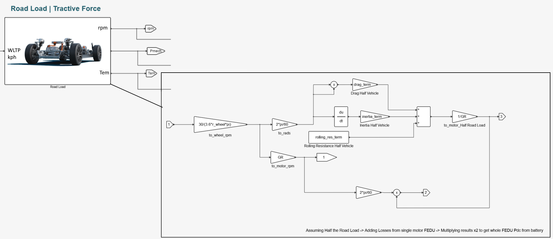
Shaft torque is derived from the required tractive force, calculated via the road load equation:
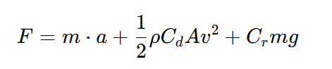
The simple road load equeation, is comprised of three parts
- Inertia Term
- Aerodynamic Drag Term
- Rolling Resistance Term
You could integrate multibody dynamics (e.g., via Altair MotionSolve), but for system-level analysis, we use this simpler equation-based approach. You can find PSIM + MotionSolve examples below:
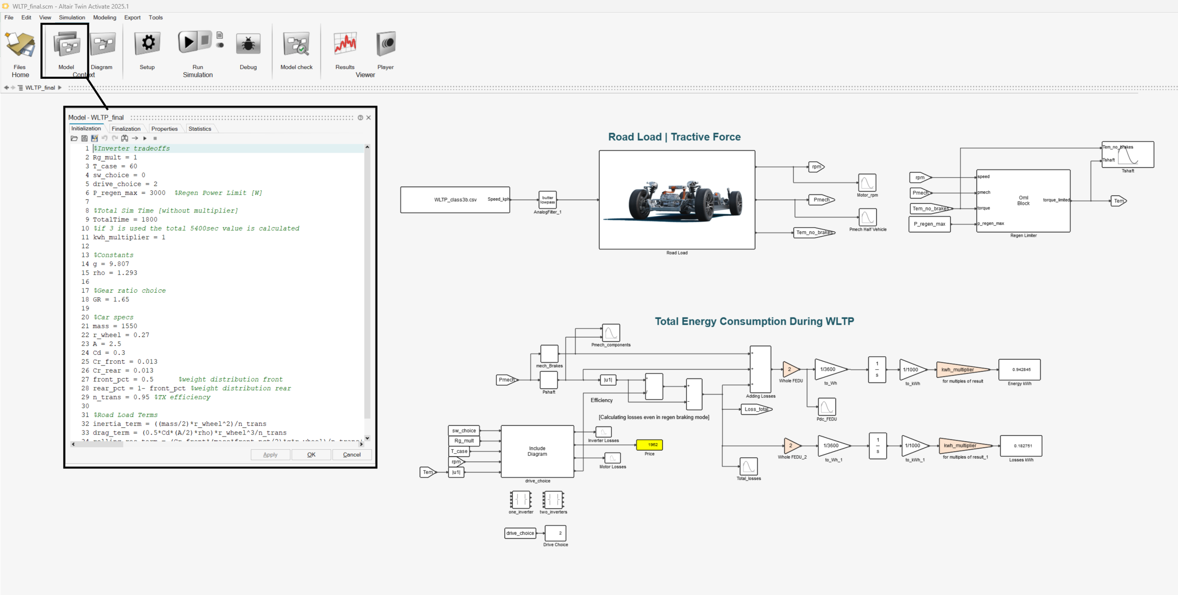
Coming back to the road load equation, we can parameterize vehicle properties such as frontal area, mass, drag coefficient, wheel radius etc. and use calculations within the "Model" panel along with math blocks to compute the torque at the wheel based on vehicle speed and road load.
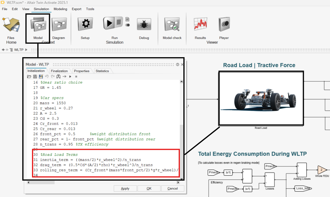
This is not yet the motor shaft torque, though. We first divide the wheel torque by the gear ratio, then determine how much of the braking is handled by mechanical brakes vs. regenerative braking.
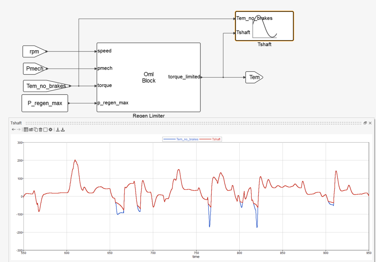
For context, "Tem_no_brakes" is the motor torque assuming 100% regenerative braking (no mechanical braking). Tem is the actual motor torque after applying the regenerative braking percentage, which will be defined in the next section.
Regenerative Braking
To control how much of the braking is handled regeneratively, we define a torque limit based on a maximum allowable regenerative power (p_regen_max). The logic is implemented using a short script block, shown below:
speed_rad_per_sec= (2 * 3.1416 * speed) / 60; % Convert vehicle speed from RPM to rad/s
torque_limit = -p_regen_max / speed_rad_per_sec; % Compute regen torque limit (negative) torque_limited = max(torque, torque_limit); % Apply limit: mech brakes cover remaining torque
In this calculation:
- torque_limit defines the maximum regenerative braking torque allowed, based on the available regenerative power (p_regen_max).
- The max() function ensures the torque never exceeds this regen limit—any excess torque demand is assumed to be handled by mechanical brakes.
This logic can be implemented inside either:
- An OML block (Altair's matrix-based scripting language)
- A Python block
Both approaches allow you to read inputs like vehicle speed, regen power limit, and initial torque, and output the actual torque at the shaft after considering regenerative braking limits.
The output mechanical power now has two components.
- The torque delivered to the motor shaft
- The braking torque handled by mechanical brakes, which results in energy loss as heat
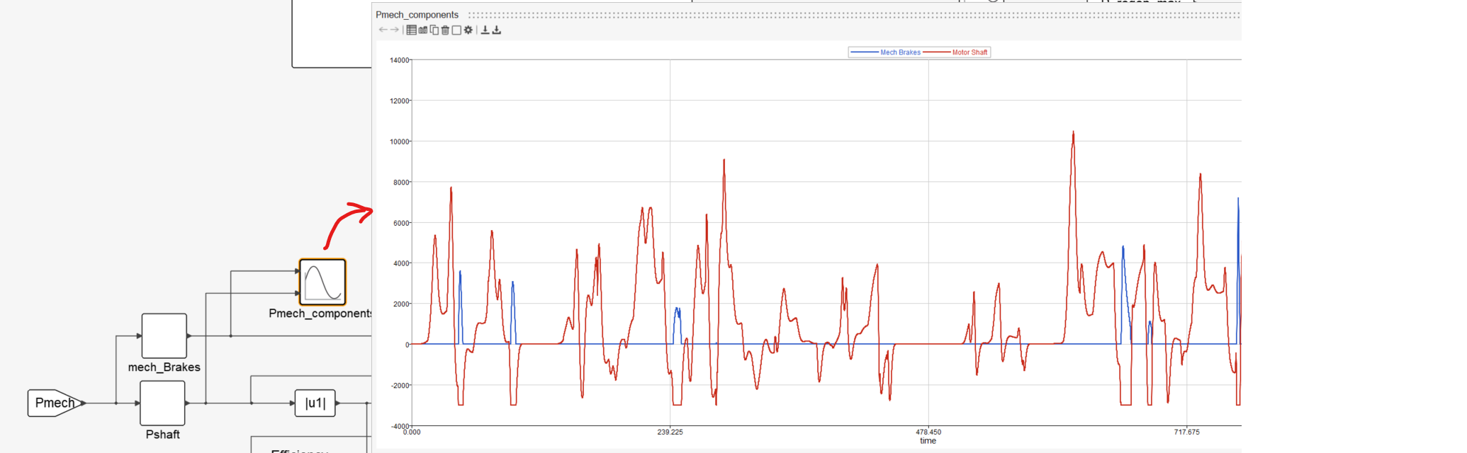
We need to calculate this (mech brake) heat loss and include it in the total energy expenditure, along with the energy used during acceleration and regenerative braking of the e-drive.
System Integration | Deploying everything in Twin Activate
Let's integrate everything together! The straightforward approach to get the energy needed for this drive cycle is to:
1. Calculate the total losses of the e-drive—both during acceleration and regenerative braking
2. Add these losses to the mechanical power (P_mech) delivered to the motor after braking.
3.Include the mechanical braking energy, which is dissipated as heat.
This will provide the total energy consumption of the vehicle.
In this example, the system consists of two motors and two inverters, both located at the rear of the vehicle. The fit models were developed based on a single inverter + motor setup:
The road load was calculated for half the vehicle as well, and we now need to multiply the final energy result x2 to estimate the total energy consumption of the whole vehicle:
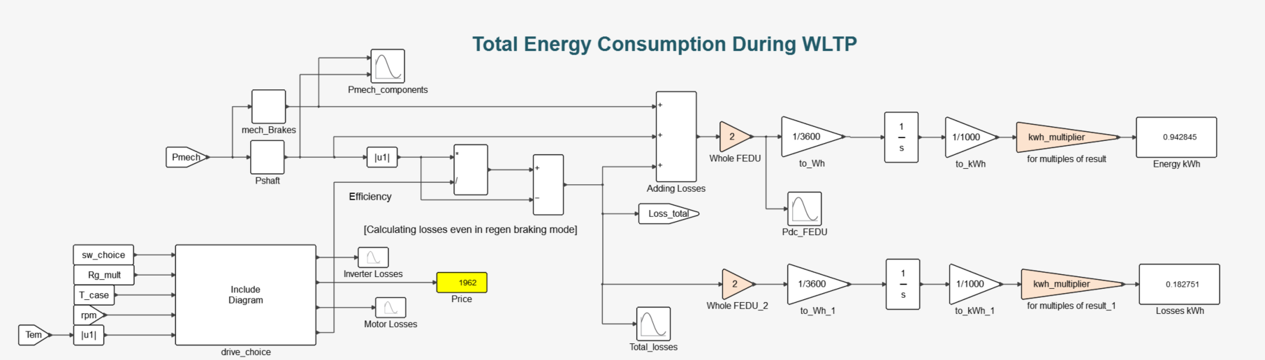
Finally, we integrate the power over time to calculate the total energy loss, and convert the result to kWh.
Note that parameters like switch selection, gate resistance, case temperature, and e-drive choice can be treated as variables and automated to explore the full design space. We can iterate between e-drives (eg. different motor) with the "Include Diagram" block.
You can use Excel files containing different battery, inverter, and motor options, along with other system-level decisions, to automate this drive cycle simulation.
This allows you to evaluate what your battery pack needs to be to meet specific energy and torque demands—even when accounting for the added weight of a larger battery.
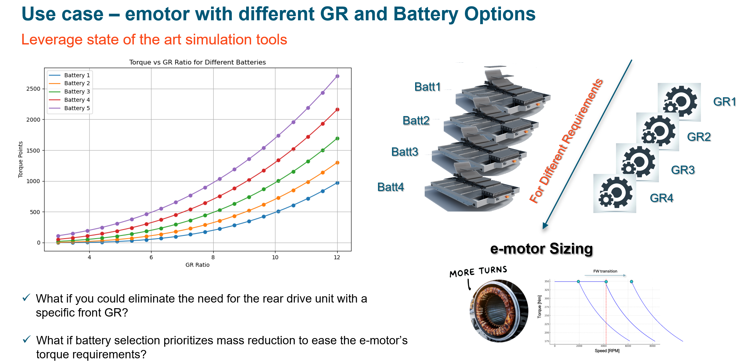
The same workflow can help you calculate the range of an EV—one of the most critical performance metrics—or the endurance event requirements in a Formula Student EV.
The complete simulation:
Simulation files:
Relevant links: