With modal superposition the dynamic response of a structure can be approximated by a superposition of a small number of its eigenmodes. This concept can be used to perform a fatigue analysis, where the stress history is obtained by multiplying modal stresses with modal participation factors and summed at each point in time:

Where σ_ij (t) is the Stress History for a given time interval for an element, P_k (t) is the Participation factor per mode at time t, σ_(ij,k) is the Modal stress of an element per mode and k the mode number.
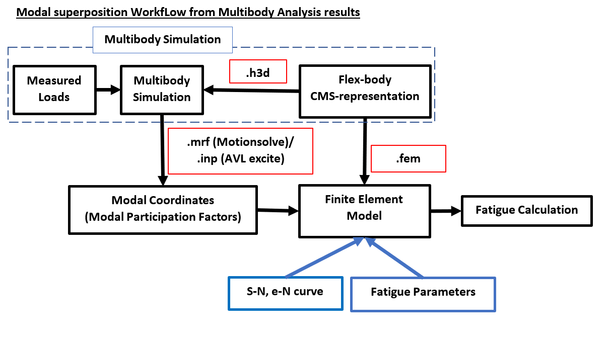
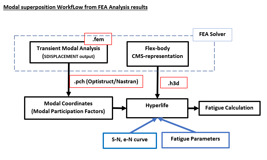
An advantage of this type of analysis is the reduction of computational time, since the model’s response is described by modal shapes and modal participation factors, where the mode shapes only need to be calculated once in a modal analysis and modal participation factors can be easily determined by any new loading definition in a multibody analysis.
Fewer mode shapes can usually provide a good approximate solution from superposition (especially when loading does not contain high frequency content).
Example:
1.Modal Superposition Fatigue Set up in Hyperworks/Optistruct.
In the residual (Fatigue) run, the Flex Body <filename>.h3d file and the .mrf results file are specified using the ASSIGN data. The ASSIGN,H3DMBD entry can be used to identify the flex-body H3D file and ASSIGN,MBDINP can be used to import the modal participation factors.

The FLEX_BODY_ID=1054 in the ASSIGN,H3DMBD data refer to the Flex Body ID's in the .mrf file.
The SUBCASE_ID=7 in the ASSIGN,MBDINP data references the SUBCASE for which the MotionSolve results will be used. In SUBCASE ID=7, instead of performing a transient analysis, OptiStruct will just use the results from MotionSolve. For transient analysis, the number of time steps in the transient analysis run must match the number of time steps used in the MotionSolve analysis. While the transient analysis data is ignored, there must still be some dummy loading data (TLOAD, DAREA, and TABLED data).
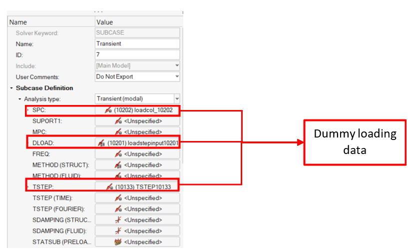
The fatigue load-map is defined using the stress history from the transient pseudo subcase.
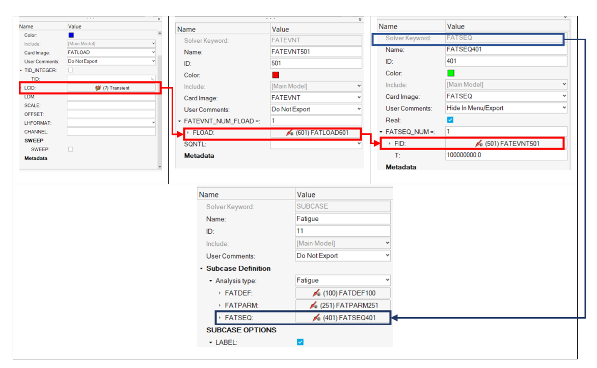
In order to define the elements that will be fatigue evaluated (FATDEF), we have to create a material with fatigue properties (MAT1+MATFAT), a PSHELL property and a SET of elements.
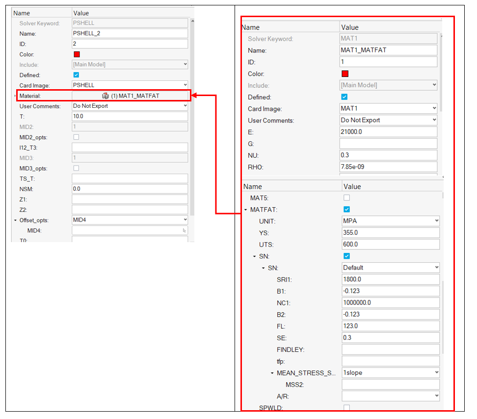
The EL2PROP Bulk Data Entry can be used to assign Property ID's' to Element sets.
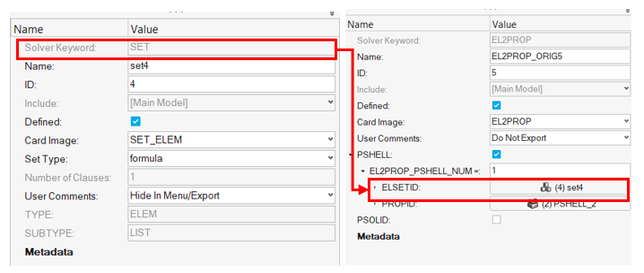
Then, the PSHELL property is refferneced in the FATDEF card as long as the fatigue properties of the elements (PFAT card).
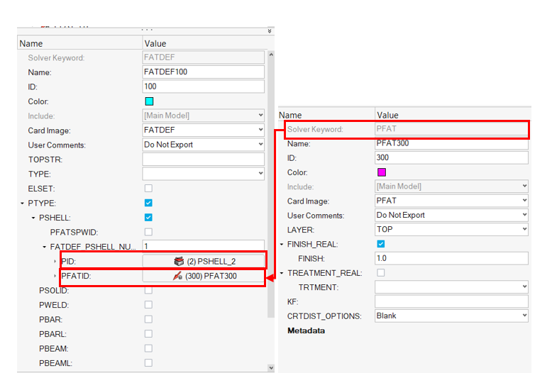
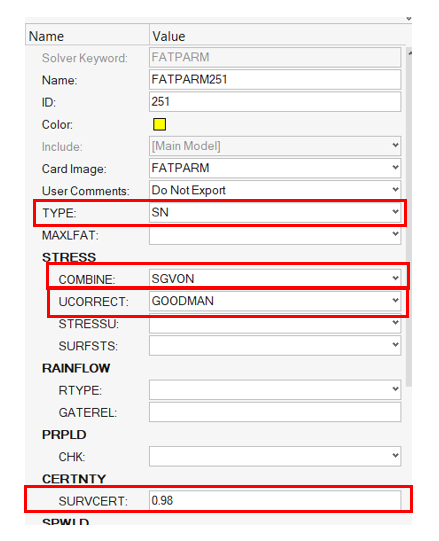
The fatigue analysis parameters are defined with the FATPARM card.
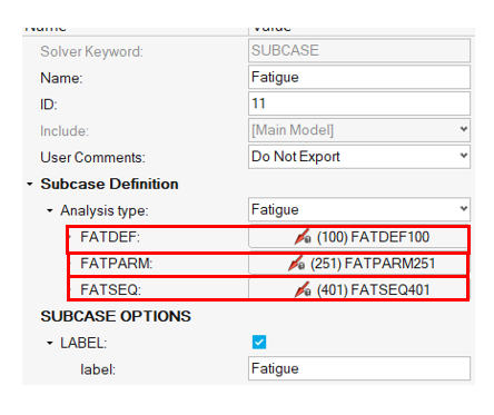
Lastly, the fatigue loadstep is created where we refence the FATDEF, FATPARM, FATSEQ cards that we have created.
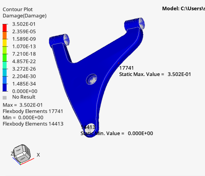
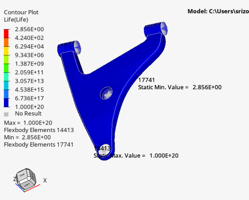
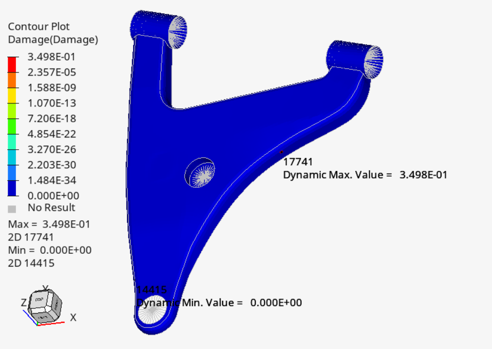
Run the analysis and review the Damage, Life results in Hyperview.
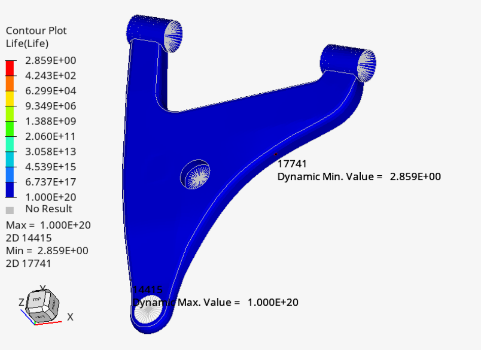
2. Modal Superposition Fatigue Set up in Hyperlife.
Import the flexbody model from the Home tools> Files tool group>Open Model tool> Load the flexbody (.h3d) file.
Define the Fatigue Module>Define the SN configuration parameters> set Type of Loading field = Modal Superposition

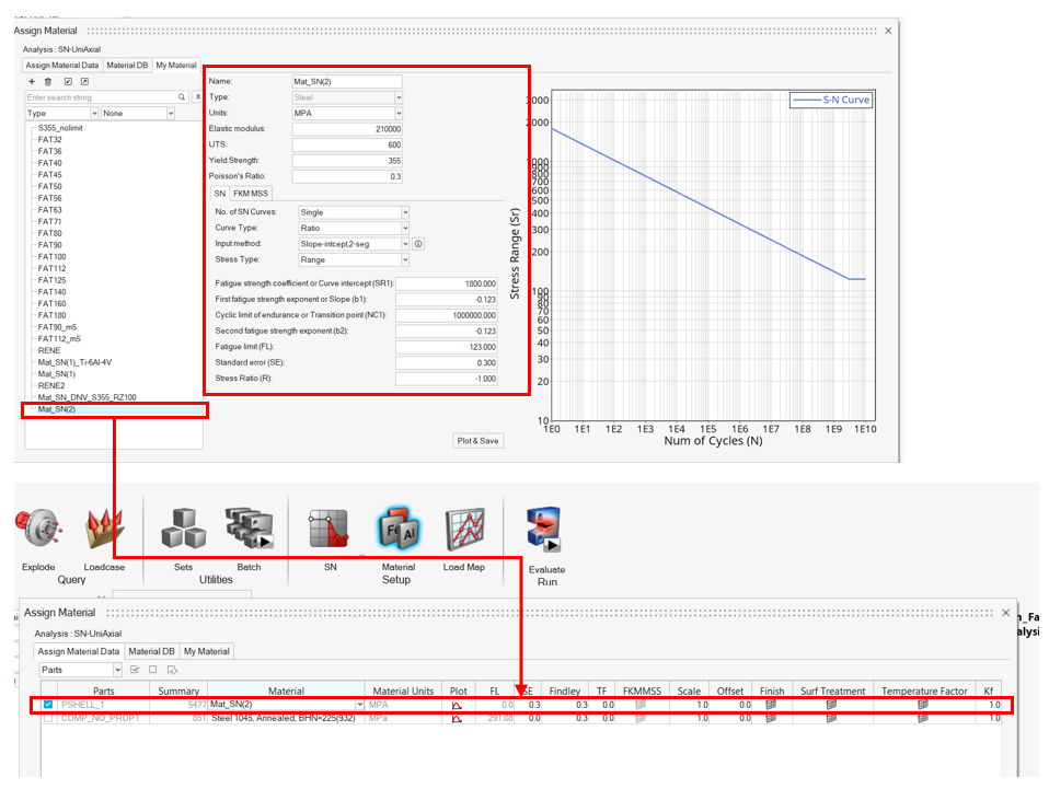
Create and assign the material.
Material BD> My Material > create a material>right click on the material in the material list > click Add to the assign material list
Create the load history> Select Subcase 1(transient) from the loaded .mrf and Modal Space from the Subcase window, to create an event with all modes > set repeats to 1.0e9
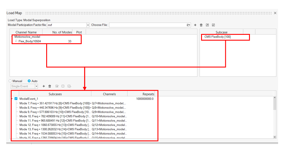
! In Hyperlife the modal participation factors can be also included via a .pch file. (This will be available in a future version of Optistruct)
Run the analysis and review the Damage, Life results inside Hyperlife.
