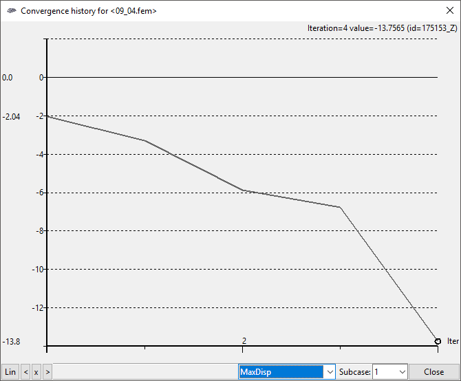
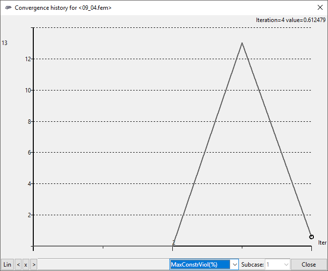
Composite Wing Free Size Optimization

Altair Forum User
Altair Forum User
Altair Employee
edited October 2020 in Community Q&A

Hello guys,


I'm working on my master thesis which is the structural optimization of a rear wing for a race car.


The wing is composed of 2 skins (top and lower) and one structural rib on the middle. All these parts are bonded together.


<?xml version="1.0" encoding="UTF-8"?>5ace1e7491d3f_plies1.thumb.png.4ba56da08c1e0ebb439827a983153cf0.png
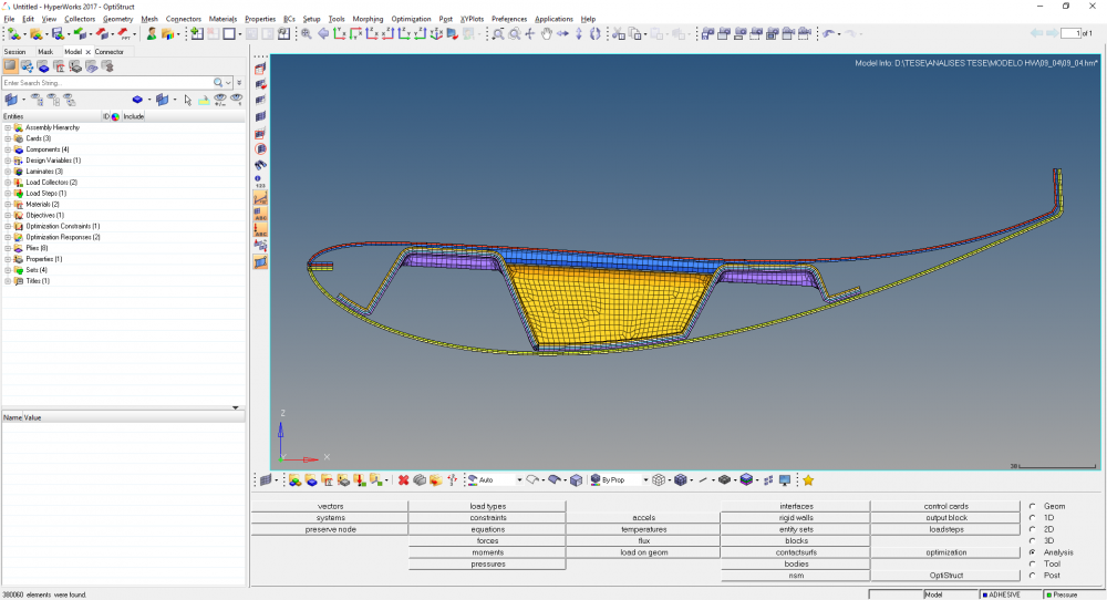
 

Here you can see the side view, the three elements of the wing with the standard lay up


<?xml version="1.0" encoding="UTF-8"?>5ace1eb830d7e_plies2.thumb.png.cbf035fb70bdf7dc5209976f5a2ea6c5.png
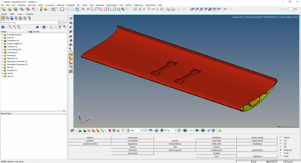
 

Here you can see the view from the Top


<?xml version="1.0" encoding="UTF-8"?>5ace1ebc0c9fd_plies3.thumb.png.6c285646f088a897bfffc08f7cd94e8f.png
 

And in here you can see the rib.


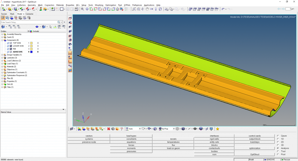
I've modeled the connection between these elements with are connectors of the rigid type:


<?xml version="1.0" encoding="UTF-8"?>5ace1eac92975_connectors1.thumb.png.b10020f637c6c85e12e1d3c773e750c8.png
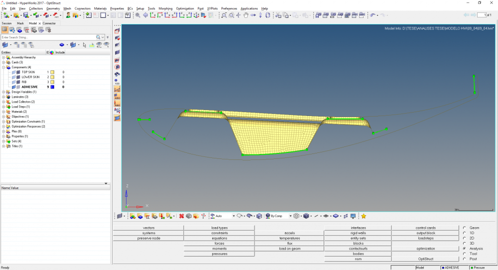
 

Connector as seen from the side.


<?xml version="1.0" encoding="UTF-8"?>5ace1eb005022_connectors2.thumb.png.191c343f5baab953fb1bb7f6908f37f3.png
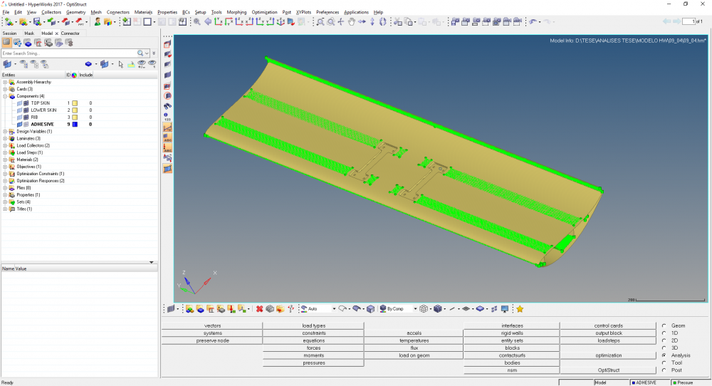
 

Connectors as seen from the top.


The wing is constrained on the middle on all 6 DOF:


<?xml version="1.0" encoding="UTF-8"?>spc.thumb.png.da0b8031c85b475f13a1b4d55e960604.png
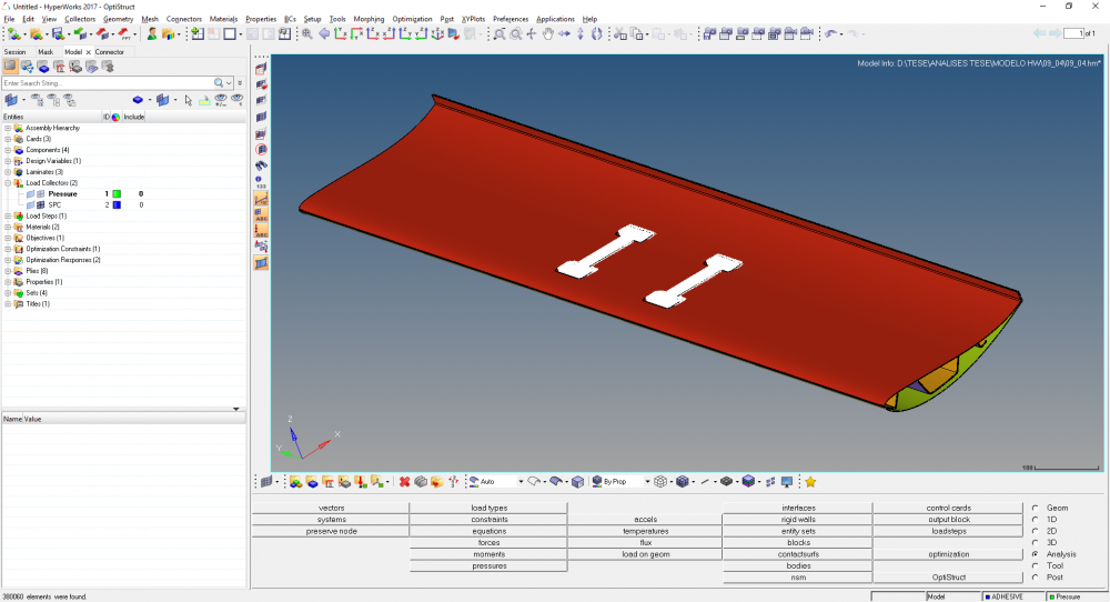
 

And on the rest of the top skin, a 400kg load is applied:


<?xml version="1.0" encoding="UTF-8"?>pressure.thumb.png.586c5f5ee533e2e4625d8f35c3bde64b.png
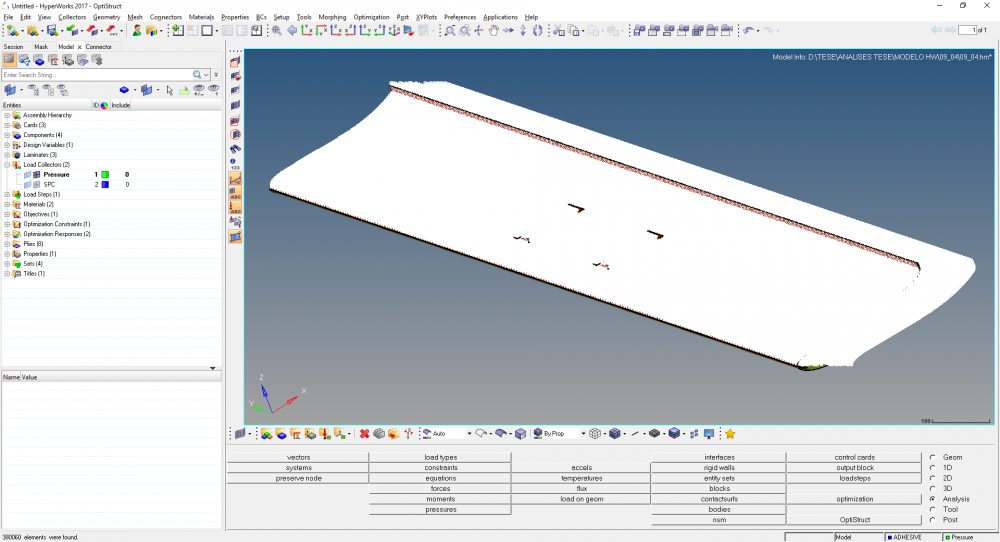
 

I've run the standard analysis and for the general lay up everything seems fine. The deformations, stresses and the failure criteria all sound plausible.


The thing is, when I try to run the first free size optimization a lot of weird things happen:


1 - It takes a LOT of time - for each iteration it takes 30min or more


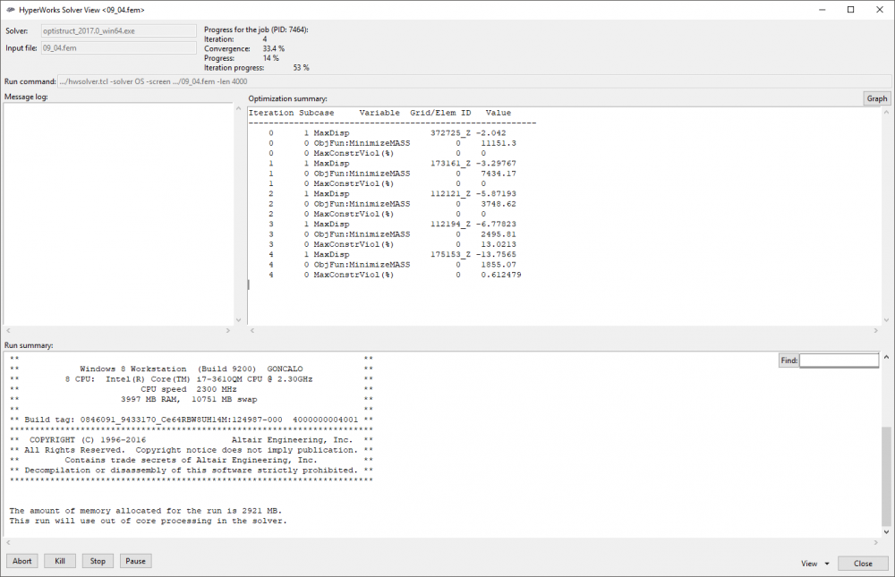
2 - It starts fine, but then it completely violates my constraints


3 - The % of constraint violation does not match


<?xml version="1.0" encoding="UTF-8"?>opt_1.thumb.png.0311003f70a958b61e5961b585decf8a.png
 

opt_2.png.72d1e5a67c6bc87aeee4e77827204c40.png


opt_3.png.5439142a88031957b3f5d21c3c9d4dbb.png


I think I've followed everything as it is supposed, but I'm not getting any decent results...


Can anybody help me?


Sorry for the long post...


Gonçalo Pimenta


PS - The plies shown above are for the general lay up (each ply with .66mm tchickness). For the analysis, I switched to 2mm. On the standard analysis I get 6mm maximum deformation on the wing and for the optimization my constraint is 6mm maximum displacement.

«1345

Answers

  • Altair Forum User
    Altair Forum User
    Altair Employee
    edited April 2018

    Hi @goncalop


    It is difficult to comment without knowing the optimization setup and other modelling parameters.


    Could you please share the model file with us?


    Please use the file transfer link in my signature to share the model file
     

  • Altair Forum User
    Altair Forum User
    Altair Employee
    edited April 2018

    Hi Prakash, thank you for the swift answer!


    I've just sent the file, please take a look at your inbox!


    Thank you very much!


    Gonçalo Pimenta

  • Altair Forum User
    Altair Forum User
    Altair Employee
    edited April 2018

    Thank you, i got the file with me. 

  • Altair Forum User
    Altair Forum User
    Altair Employee
    edited April 2018

    Hi @goncalop


    try this,


    Instead of selecting too many nodes, select the node with maximum displacement on each side and use these two nodes for Displacement constraint. Since there are too many nodes for displacement constraints, it is taking long for calculation. 

  • Altair Forum User
    Altair Forum User
    Altair Employee
    edited April 2018

    Hi @Prakash Pagadala,


    I'll try that right now!


    Thanks for the feedback!


    Gonçalo Pimenta

  • Altair Forum User
    Altair Forum User
    Altair Employee
    edited April 2018

    Hello @Prakash Pagadala,


    Unfortunately, I still don't think that the nodes are the problem.


    Currently I'm running a simulation like you suggested and after 30min is still on the first iteration...

  • Altair Forum User
    Altair Forum User
    Altair Employee
    edited April 2018

    @goncalop


    I will check and come back to you soon.

  • Altair Forum User
    Altair Forum User
    Altair Employee
    edited April 2018

    Thank you very much!


    Looking forward for your feedback!


    PS - One question: Do you think it may be taking so long (and not getting proper results) due to the number of RBE2 elements on the Area Rigid Connection?

  • Altair Forum User
    Altair Forum User
    Altair Employee
    edited April 2018

    @goncalop


    Is there a reason for using element size of ~2?


    You can increase the element size to reduce the number of nodes which can improve the analysis time. 


    Also, you can specify the amount of memory to use using -minlen and -maxlen 

  • Altair Forum User
    Altair Forum User
    Altair Employee
    edited April 2018

    @Prakash Pagadala


    I used the element size of 2 due to a convergence analysis I did (see below).


    <?xml version="1.0" encoding="UTF-8"?>image.thumb.png.aef4b14722b5a3459bcee3e5e817bc42.png


    Nº ELEMENTOS is the number of elements.


    I usually let the analysis run with the default memory.. Only with the standard analysis for 1mm elements it asked me for almost 7gb. For every other analysis I've run, it only used 4gb maximum

  • Altair Forum User
    Altair Forum User
    Altair Employee
    edited April 2018

    OK, element size makes sense then,


    You can increase the memory and check if that helps. 

  • Altair Forum User
    Altair Forum User
    Altair Employee
    edited April 2018

    <?xml version="1.0" encoding="UTF-8"?>image.thumb.png.99fdbaa1020a63bd535f5bd92552f225.png


    I'm running this one since 10:27:41 (almost 90min ago) and it is currently starting to violate the constraints. But as you can see on the right, on iteration 2 it already violated the 6mm constraint but still the MaxConstrViol (%) is still 0.. - it violated it by +-7%


    I allocated 4000mb for this run but it still doesn't use more than 2000mb +-


    Sorry for the trouble..

  • Altair Forum User
    Altair Forum User
    Altair Employee
    edited April 2018

    Hi,


    You have allocated maximum allowable memory, which is the upper limit, right?


    Which means solver will still automatically choose memory but will not exceed 4000Mb. 


    Looks like on screening the violation is rounded off to zero, can you check the same in .out file?


  • Altair Forum User
    Altair Forum User
    Altair Employee
    edited April 2018

    Yes, true... I have allocated the maximum allowable memory indeed...


    <?xml version="1.0" encoding="UTF-8"?>image.thumb.png.e9582fbe7cc4173998b88aecf0416083.png


    Here is the Current Output File. It looks like the response is in fact lower than the one presented on the main window

  • Altair Forum User
    Altair Forum User
    Altair Employee
    edited April 2018

    You can use -minlen and -maxlen to put limits on memory usage. 


    Also, the node ID displaced on screen is not same as .out right?

  • Altair Forum User
    Altair Forum User
    Altair Employee
    edited April 2018

    Can you please tell me how I use maxlen? Can I find it on the control cards?

  • Altair Forum User
    Altair Forum User
    Altair Employee
    edited April 2018

    If you are not using Student Edition, use Solver manager to set it

    <?xml version="1.0" encoding="UTF-8"?>RUnoptions.PNG

  • Altair Forum User
    Altair Forum User
    Altair Employee
    edited April 2018

    I would suggest you set minlen so that OptiStruct uses a minimum limit. 

  • Altair Forum User
    Altair Forum User
    Altair Employee
    edited April 2018

    You can also use SYSSETTING but you need to explicitly define this in your solver file. 


    Please let me know if you have any trouble with this. 

  • Altair Forum User
    Altair Forum User
    Altair Employee
    edited April 2018

    You can also provide memory details as shown in image: 

    <?xml version="1.0" encoding="UTF-8"?>RUnoptions.PNG

  • Altair Forum User
    Altair Forum User
    Altair Employee
    edited April 2018

    You can also provide memory details as shown in image: 

    <?xml version="1.0" encoding="UTF-8"?>RUnoptions.PNG


    I'm using this right now.


    I'll let it run for a while and when I have news I'll post it here!


    Thank you so very much!

  • Altair Forum User
    Altair Forum User
    Altair Employee
    edited April 2018

    Even with minlen defined to 4000mb, it's still using only 1800mb of ram... and taking the same time I think...


    <?xml version="1.0" encoding="UTF-8"?>image.thumb.png.aab78a7c7d1f3db2b403e4a0db45a524.png

  • Altair Forum User
    Altair Forum User
    Altair Employee
    edited April 2018

    OK, I am going to check this with experts and I will get back to you soon. 

  • Altair Forum User
    Altair Forum User
    Altair Employee
    edited April 2018

    @Prakash Pagadala


    The simulation is still running but it's actually using something more like 3800mb on average.


    The speed doesn't seem to have been affected though...

  • Altair Forum User
    Altair Forum User
    Altair Employee
    edited April 2018

    <?xml version="1.0" encoding="UTF-8"?>image.thumb.png.2d819ef46f9040768a88563b0099785b.png


    @Prakash Pagadala


    Take a look at the screen attached. From now on it starts getting really weird with the displacement. The values on the control screen and on the output file do not match

  • Altair Forum User
    Altair Forum User
    Altair Employee
    edited April 2018

    <?xml version="1.0" encoding="UTF-8"?>image.thumb.png.559e360408c4fca372fa2326d1ec5159.png


    @Prakash Pagadala


    After iteration 5 these are the results.


    Do you think it is possible that during the optimization process, the maximum displacement point shifted from the ones where we applied the constraints?

  • Altair Forum User
    Altair Forum User
    Altair Employee
    edited April 2018

    Hi @goncalop


    Sorry for a late reply, 


    As you can see from the .out file, the displacement you see on the left and on the right is not for the same grid. They are different. 


    Please check if the grid with maximum displacement is a part of the design at all. 

  • Altair Forum User
    Altair Forum User
    Altair Employee
    edited April 2018

    Hello @Prakash Pagadala,


    What do you mean with grid? The nodes are aligned and part of the same component I think 

  • Altair Forum User
    Altair Forum User
    Altair Employee
    edited April 2018

    Hi,


    I have your file, 


    Let me check and get back to you. 

  • Altair Forum User
    Altair Forum User
    Altair Employee
    edited April 2018

    @Prakash Pagadala,


    Did you get the files I sent you on Friday?


    Do you think there could be something wrong with the area connectors? 


    I say this because of these results


    <?xml version="1.0" encoding="UTF-8"?>3.thumb.png.315ac5c450cc2a53efb5a4f0623b04f5.png