Composite Wing Free Size Optimization
Answers
-
Hi @goncalop
Try one laminate or few plies at a time with smoothing iteration =0 if you want to save the ply shape as it is and export to .stp
0 -
I'll try one ply at a time, but I've tried just one laminate before and the the result is the same... It freezes.
Do you have any suggestion to make this whole optimization process run faster? I think this is taking a bit too long for a relatively simple component..
0 -
It took 20 mins to get surfaces for 10 plies. Again it depends on the model size and computation power.
0 -
I'm doing exactly what you suggested right now, but it gets stuck on ply 3 for an awful long time. I'm trying just the first 10 plies as suggested
These are the settings I chose. It currently says not responding but I think it is still making some calculations...
0 -
0
-
Please wait for some more and if still, nothing comes up, I shall report this to developers.
0 -
0
-
Hello @Prakash Pagadala, how are you?
Do you have any news regarding the topics mentioned above?
Thanks!
Gonçalo Pimenta
0 -
Hello @Prakash Pagadala, how are you?
Sorry to bother you again but I have been working on my model and I have two questions:
1 - As you know, my goal is to reduce the weight of the wing and I've been running optimizations with the objective to minimize the overall compliance while I have the volumefrac restricted. I've been getting some nice results but I wanted to try this:
<?xml version="1.0" encoding="UTF-8"?>Under load I want to make the gurney flex a little so I created a node between the two bonded surfaces, connected both surfaces to the node with rigid elements and applied a vertical load. The static analysis works as intended.
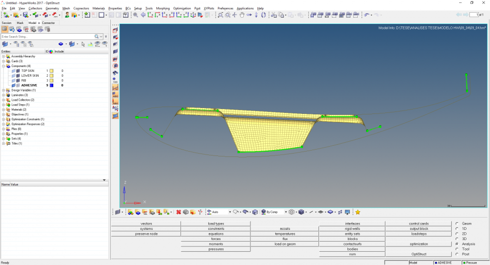
Do you have any suggestions to put this on the objective functions? I thought about a weighted compliance but for this loadstep (flexing the gurney), I would want to maximize it.. I don't know how I can achieve this.. Constrain the volumefrac and minimizing the compliance of the wing while allowing some flex on the edge. Do you have any suggestion?
2 - On some areas on the wing I would like to constrain the maximum thickness like on the areas highlighted below:
<?xml version="1.0" encoding="UTF-8"?>
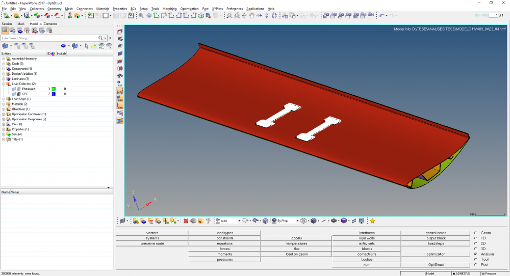
I tried the Zone Based menu on the design variables but I can't seem to get it to work... Do you have any suggestion?
Once again, thank you so much for your time!
Gonçalo Pimenta
0 -
Hi,
Constrain the volumefrac and minimizing the compliance of the wing while allowing some flex on the edge. Do you have any suggestion?
Try with minimizing mass as objective and bounds on displacement.
0 -
Altair Forum User said:
2 - On some areas on the wing I would like to constrain the maximum thickness like on the areas highlighted below:
Does it include constraining thickness of plies?
You can use CONST on Disze card, Indicates that a constant thickness constraint is applied. Multiple CONST constraints are allowed.
0 -
Minimizing mass with a constraint on the displacement was the first optimization I was doing and the results were completely erratic. That was why I switched to minimize compliance with the volume fraction constrained.
Regarding the thickness, I was aiming to give a maximum thickness to the laminate on that specific area. On the design variable menu you can choose the maximum or minimum laminate thickness but they are general thicknesses and I was looking for a local constraint... The thickness of the Plies could be whatever the solver wanted it to be as long as the thickness of the laminate would not exceed the given value...
0 -
Altair Forum User said:
Minimizing mass with a constraint on the displacement was the first optimization I was doing and the results were completely erratic. That was why I switched to minimize compliance with the volume fraction constrained
Try this during the sizing optimization instead of free size for that particular laminate.
0 -
Altair Forum User said:
Regarding the thickness, I was aiming to give a maximum thickness to the laminate on that specific area. On the design variable menu you can choose the maximum or minimum laminate thickness but they are general thicknesses and I was looking for a local constraint... The thickness of the Plies could be whatever the solver wanted it to be as long as the thickness of the laminate would not exceed the given value...
You are right, laminate constraints are applied to the entire laminate.
As a workaround, you can define the local area/volume as a separate laminate and you can apply laminate constraint for that.
0 -
Hello @Prakash Pagadala, how are you?
I've been working on the model and getting some nice results. Splitting the design variables and constraining the zones where I want a defined thickness is indeed working.
Before I proceed to the size optimization I would like to get the ply shapes to something more manufacturable.
This is what I have right now:
<?xml version="1.0" encoding="UTF-8"?>
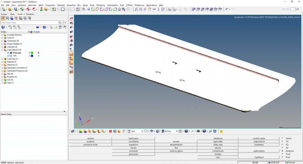
Now, from what I read and from what you told me I have two options: I can either use OSSMOOTH or Ply Geometry Smoothening from the Aerospace Menu.
I've tried Ply Smoothening before but for some reason I can't get it to work as intended (it freezes or it doesn't create any .stp file) and I've been trying to work with OSSMOOTH and I think it is working to some extent (at least the number of plies is reducing).
Before I proceed I wanted to know if you could explain me better what each of the options does on each case:
OSSMOOTH:
<?xml version="1.0" encoding="UTF-8"?>
Select Model - I select the .fem file for which I want to smooth the plies (on my case, I've used the result of the free size optimization)
Output File - OSSMOOTH will output a .fem file with the smoothed plies which I'll have to import to a model later
Smooth Iterations - How many times OSSMOOTH iterates each ply until the best shape is achieved?
Small Region, Area Ratio - The minimum area ratio for each ply? If I choose 0.4 the minimum ply area is 40% of the total area?
Split Disconnected - If a ply has more than one area that is not connected, it splits the ply in different plies for each zone
Create Geometry - ???
Ply Geometry Smoothening:
For this one I need a little bit more help. While OSSMOOTH writes to a different .fem file, this one works on the current .hm file.
I don't understand the geometry collector and geometry creation parts (where does it create the geometry?).
The smooth Iterations and small region I think work the same as in OSSMOOTH right? The same goes for split disconnected ply regions...
Update ply element sets I also do not know what it does.
Export surfaces and lines is self explanatory I think but I can't get it to work.. even with 0 iterations..
Sorry for such a lengthy post but I'm really trying to make a good project and I can't seem to find anything to properly answer this questions on the internet..
Thank you so much for your help!
Gonçalo Pimenta
0 -
Altair Forum User said:
Select Model - I select the .fem file for which I want to smooth the plies (on my case, I've used the result of the free size optimization)
Output File - OSSMOOTH will output a .fem file with the smoothed plies which I'll have to import to a model later
Smooth Iterations - How many times OSSMOOTH iterates each ply until the best shape is achieved?
Small Region, Area Ratio - The minimum area ratio for each ply? If I choose 0.4 the minimum ply area is 40% of the total area?
Split Disconnected - If a ply has more than one area that is not connected, it splits the ply in different plies for each zone
Create Geometry - ???
Hi,
I would go with default to start with and create geometry is not required unless you want to take the ply shape to any CAD tool. SPlit works on entire ply.
Altair Forum User said:I don't understand the geometry collector and geometry creation parts (where does it create the geometry?).
It creates either as a seperate component or a mixed geometry of all plies in the same component.
0 -
Thanks for the swift reply.
Altair Forum User said:create geometry is not required unless you want to take the ply shape to any CAD tool
I need to output the ply shapes to cad so I can create the ply geometries to use on the plybooks and to later cut the plies to layup on the mould.
This is why I need them with a nice shape.
When I select create geometry on OSSMOOTH it doesn't give me any option to create an stp file like on Ply Geometry Smoothening. How do I make it output the .stp file?
Thanks!
0 -
In such a case I prefer to use Ply geometry smoothing and select few plies at a time instead of all and export the geometry
0 -
So, instead of going for OSSMOOTH, I go for Ply Geometry Smoothening for a few plies at a time while exporting the .stp files? With the default settings?
If I choose a area ratio of 0.4, what happens to the plies that have a area ratio smaller than the one I chose?
Also, the area ratio is calculated regarding the whole area of the model? Or the area of the original set?
Thanks!
0 -
Altair Forum User said:
So, instead of going for OSSMOOTH, I go for Ply Geometry Smoothening for a few plies at a time while exporting the .stp files? With the default settings?
Yes,
Altair Forum User said:Also, the area ratio is calculated regarding the whole area of the model? Or the area of the original set?
I need to check regarding this. I will get back to you on this.
0 -
Hi,
Area ratio: local region area / total design area (real value between 0.0 and 1.0. Default=0.01)
0 -
So, if I have more than one design variable, the area is the sum of all the design areas?
In my case, the total area is the lower skin + rib + top skin?
0 -
I tried doing what you told me but it freezes and doesn't give me any results.
I tried running some tutorials and everything seems fine - for example, on OS-3400 I can get 20 to 400 iterations, different area ratios and I always get a result in no time.
With what I'm doing although, it takes a awful long time and it doesn't seem to do anything at all. Smoothening the plies is the last thing I have to do since the size optimization and shuffle optimization is possible (I've done it) but the plies shape is terrible for manufacture.
Do you have any advice in order to get it to run faster?
Thank you very much!
Gonçalo Pimenta
0 -
I think that is because of the huge number of nodes and not available of sufficient memory,
I will check with experts for their advice on same.
0 -
I sent you some files yesterday so you can check better with my fem.
Thank you for your help. I have a workstation available with a Xeon E5-1603 and 16gb of ram but the result is the same I guess...
I can try leaving it more than a day but I think that one day is already too long... When I press OK the result is the same as the one I sent you by file transfer. CPU and RAM usage, no disk writing and Hyperworks no responding.
Thank you for your help!
Gonçalo Pimenta
0 -
0
-
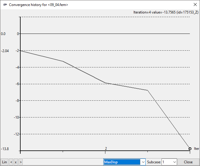
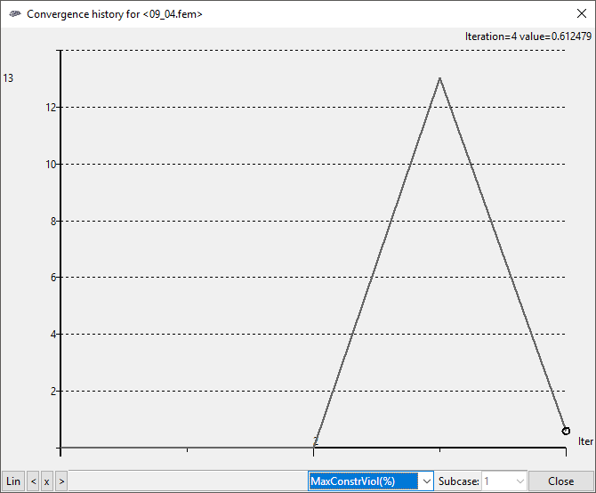
I ran some things today and I finally got results:
I first ran OSSMOOTH with 40 smooth iterations and a area ratio of 0.4. - Both split disconnected and create geometry were left unchecked.
Then I ran Ply Geometry Smoothening with a separate component for each ply, 0 Smooth iterations and the same area ratio as OSSMOOTH. I then checked update ply element sets and exported the surfaces to an .stp file.
The Xeon workstation managed to do this in 2 hours or so, so it's not so bad.
With this, I have a few questions:
1 - What is the true meaning of area ratio and how it affects the final result
2 - Smooth iterations? The more I choose the smoothest my final ply?
3 - How can I get symmetric plies? See below, some of the plies created are not symmetrical even thought the load is a constant pressure
<?xml version="1.0" encoding="UTF-8"?>
Also, how do I prevent small zones like the one below? I thought that was done with area ratio. Should I check split disconnected so it can clean them?
<?xml version="1.0" encoding="UTF-8"?>
Thank so much for your help! I look forward for your feedback!
Gonçalo Pimenta0 -
Hi,
Glad that you are able to get the shapes, I am checking with experts on ply geometry tool.
The area ratio is the local patch area/ total area of the ply,
Though the load is symmetric, optimized results may not be symmetric. You can add symmetric pattern grouping constraint before you start the analysis.
Please refer to attached PDF for more information
0