NOTE: A solid, in-depth understanding of MotionView for vehicle modeling and OptiStruct for structural analysis is essential to successfully implement this type of MotionSolve–OptiStruct co-simulation workflow.
*Refer to the attached folder, containing detailed process of the MS-OS Cosim workflow along with all the model setup files.
As electrification continues to shape the automotive landscape, virtual validation of electric vehicle (EV) sub-systems such as battery enclosures becomes essential. Capturing nonlinear deformation and contact behavior under dynamic loads—such as hitting a road bump—requires both the flexibility of multibody simulation (MBD) and the structural fidelity of finite element analysis (FEA).
This article walks through a structured co-simulation workflow using Altair MotionSolve and OptiStruct, centered on a two-wheeler EV battery pack encountering a road bump.
Software & File Setup
Ensure you're using Altair 2024.1 or later for both MotionView/MotionSolve and HyperMesh. The attached folders includes:
- MS_OS_Base:
- CMS_Battery_Pack_files: Contains .fem and .h3d files for CMS linear Flexbody(
CMS_Battery_Pack.fem) - Standalone_MS_Results: Contains only Motionsolve run from Phase 1 of this tutorial, to get the coordinates at 0.3s
- Electric_Bike_BASE_archive.zip: MotionView archived model(
Electric_Bike_BASE.mdl)
- MS_OS_Final:
- Electric_Bike_FINAL_archive.zip: Contains the final MDL file from Phase 2 and 3, which can be used for cosimulation directly (
Electric_Bike_FINAL.mdl, OS_Battery_Pack.fem) - MS_Solver_Deck_to_Create_template: Contains solver files from Motionsolve which helps in creating the template from Phase 2
- MS_OS_Solver_files: Complete final solver deck which can be run directly for MS-OS Cosimulations
- MS_OS_Results: Final MS-OS cosimulation results
Phase 1: Prepare the Linear Model & Get Joint Displacements
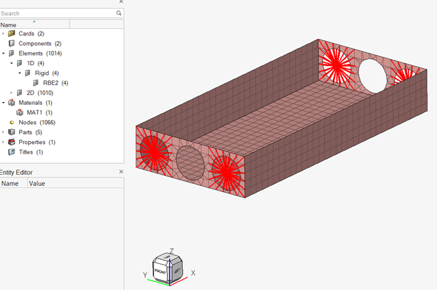
Start by creating a 2D shell FEM for the battery pack in HyperMesh, using linear material and RBE2 connections at four mounting points. These RBE2 independent node coordinates must match the joint locations in the MotionView model.
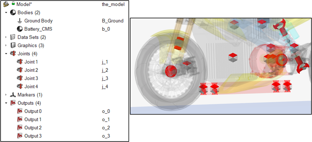
After importing this FEM into MotionView and generating the CMS flexbody using FLEXPREP, embed it into your two-wheeler MBD model using fixed joints. Use Altair Driver to simulate a standard double lane change (DLC) event with a velocity of 5555.56 mm/s (=20 kmph)
During postprocessing, determine the time just before the front tire contacts the bump—0.3 seconds in this case. At this instant, extract the X, Y, Z displacements at the four joint locations. These values will be used as input constraints in OptiStruct to match positions across solvers.
Output Name | X | Y | Z |
|---|
Output 0 | -1675.06000 | 0.90360 | 15.95520 |
Output 1 | -1675.14000 | 0.90371 | 15.77040 |
Output 2 | -1674.83000 | 1.15542 | 33.44230 |
Output 3 | -1674.90000 | 1.15528 | 33.25740 |
Phase 2: Set Up Nonlinear OptiStruct FEM & Time Synchronization
Create a new OptiStruct FEM with nonlinear material for the battery cover and a bump modeled as a shell surface, aligned with the road bump defined in MotionView.
Define:
- 5 SPCs: 4 for battery pack nodes and 1 for bump RBE2 node
- 12 SPCDs: For the displacement values at 0.3s, derived from Phase 1
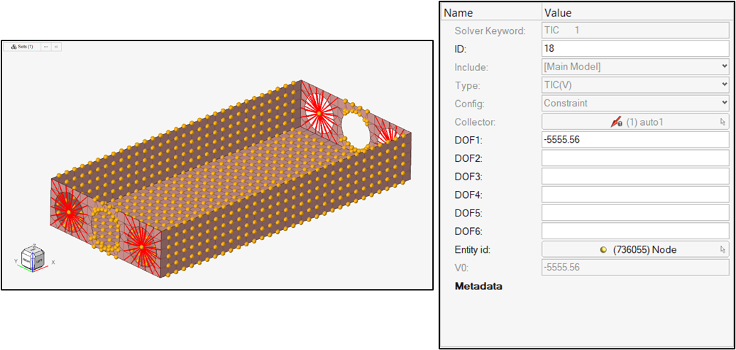
- TIC_SET: All battery nodes except RBE2 dependents, to initialize velocity
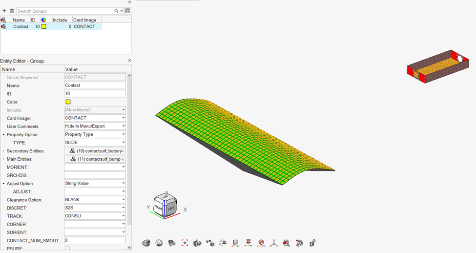
- CONTACT: Define two surface sets—battery and bump
In MotionView, add this nonlinear FEM as a new OS Flexbody. Create four spherical joints at the RBE2 node locations. Create the following solver strings in motionview:
MSI_START_TIME = 0.3MSI_TIME_OFFSET = -0.7 (because total sim time is 1s)
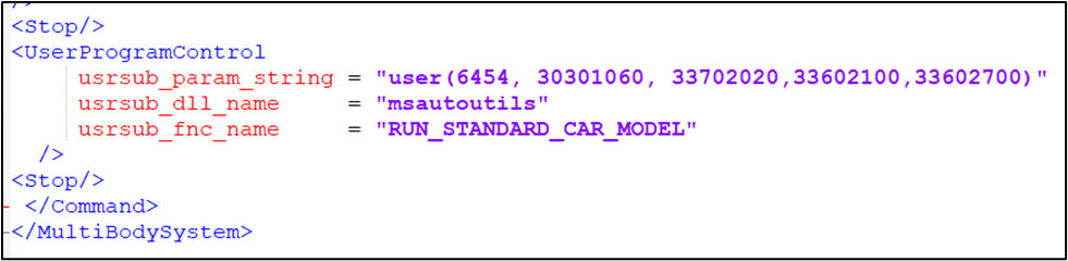
Export the model to XML and create a template to insert the required UserProgramControl block for co-simulation execution.
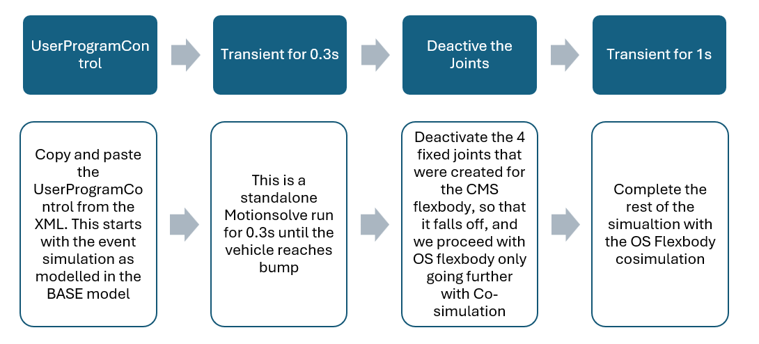
Go back to the motionview model and Create a template, with the type as “Write Text to solver command file”. The sequence of simulation using template is as follows:
Phase 3: Finalizing Simulation Parameters
Modify Driver File
Edit the .adf file:
- Set simulation time to 0.2s
- Set print interval to 0.001s
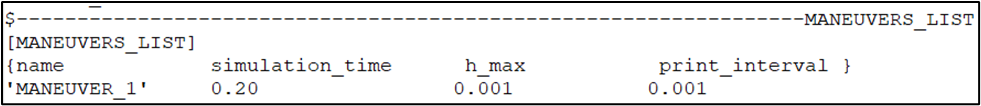
This ensures alignment with OptiStruct’s print steps and allows for motorcycle stabilization at the beginning.
Modify FEM for Co-Simulation
Open the newly generated .fem from MotionView and adjust the following:
- Delete the
OUTPUT card - Set TSTEP5: 700 steps with 0.001 increment
- Create NLPARM_static load collector
- Create SPCADD load collector combining battery and bump SPCs
- Define two subcases: one static (for initial condition match) and one nonlinear transient
Export the updated FEM file to the same directory as the XML and ADF files. Refer to the attached document in the folder, which explains each of the above parameters in the FEM file.
Running the Co-Simulation
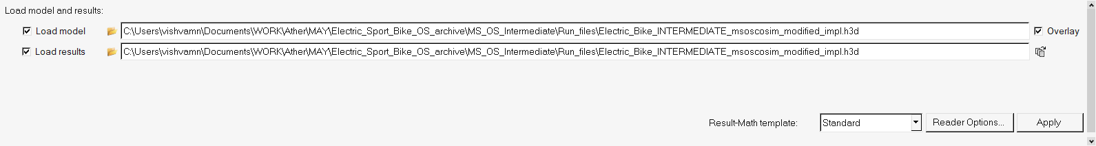
Ensure the working directory contains:
Electric_Bike_FINAL.xmlElectric_Bike_FINAL.adfElectric_Bike_FINAL_msoscosim.fem
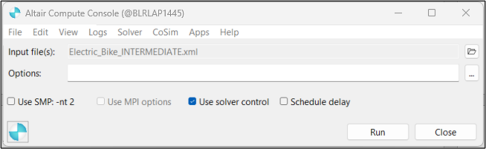
Step 1: Open Altair Compute Console with MotionSolve. Load the XML and run. It will wait for coupling.
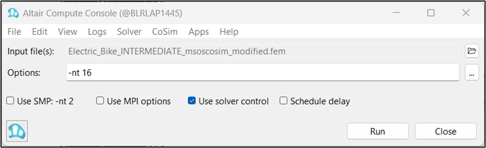
Step 2: Open another console with OptiStruct, load the modified FEM, and start the run.
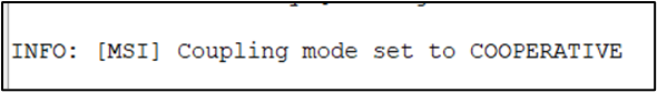
Now the two solvers are coupled and will simulate concurrently, with proper time and motion synchronization.
Post-Processing Results
Open the .h3d file from MotionSolve in HyperView and animate the results. At 0.3s, the CMS battery flexbody should detach from the frame as joints deactivate.
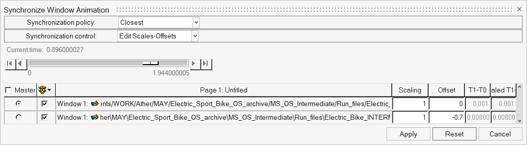
Overlay the OptiStruct .h3d file (Electric_Bike_FINAL_msoscosim.h3d) and apply a time offset of -0.7s for synchronization.
Contour plots such as elemental stresses or contact forces can now be visualized using the transient subcase data from OptiStruct. Further outputs like strain or energy can be enabled via GLOBAL_OUTPUT_REQUEST in the FEM file.
NOTE: The other required outputs like strains, contact forces etc can be enabled in the .fem file (GLOBAL OUTPUT REQUEST) as required for the application.
Conclusion
This structured co-simulation between MotionSolve and OptiStruct not only demonstrates a realistic road impact scenario for a battery pack but also sets a framework for more complex coupled analyses involving dynamic loads and nonlinear material behavior.
By leveraging the strengths of both MBD and FEA domains, engineers can now virtually test systems earlier in the design process—accelerating development, reducing prototypes, and improving safety.
Click on the following link for MODEL files