INTRODUCTION
Iron roughnecks are hydraulic devices widely used in the oil and gas industry for the automation of critical operations on oil rigs. Historically, these systems were introduced to improve the safety of oil rig workers while connecting and disconnecting drill pipes. Without such systems, these operations would be performed manually, posing a high risk to workers as they are carried out under very high loads. Today, iron roughnecks play a vital role in drilling automation. Combined with other automated equipment, these iron roughnecks enable safe and automated drilling operations.
In this article, we will explore the creation of a Multibody Dynamics (MBD) model of the iron roughneck using Motion View (MV) to understand various loading conditions, and we will also study the integration of this MBD model with a hydraulic control system using Twin Activate (TA).
Designing an iron roughneck is a multidisciplinary problem. It is a complex multibody system that typically has many degrees of freedom (10+) to account for its various functions. Additionally, the system is hydraulically driven, with hydraulics playing an important role in its operation.
WHAT ARE THE IMPORTANT ASPECTS OF DESIGN ?
STRUCTURAL
The system needs to handle very high loads (up to 145,000 ft-lbs) to connect and disconnect pipes. Engineers need to study the system from an MBD perspective to understand the loads on its various components and linkages, ensuring structural robustness. Various operations include – wrenching, gripping, guiding, spinning
HYDRAULICS & CONTROL
Studying the hydraulic system is important to ensure that it meets key performance requirements such as safety, efficiency, and control
Safety – As these systems operate with humans in the loop, additional safety criteria such as maximum speed and acceleration are also imposed to avoid injuries in the field.
Efficiency – Power consumption of the hydraulic systems needs to be studied to optimize operations for better efficiency.
Control – Controller gains can be tuned to meet the system's performance requirements.
PREREQUISITE
Altair MotionView 2025
Altair MotionSolve 2025
Altair Twin Activate 2025
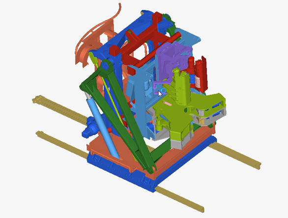
UNDERSTANDING THE MODEL DEFINITION IN MOTIONVIEW
Loads on various components are not static; instead, they vary as the iron roughneck performs various operations. An MBD model can help capture these variations by representing the material properties and connections among the system's components.
Most MBD models start with a CAD model. After creating the CAD geometry (not covered in this article), model setup is broadly carried out in the following steps
- CAD clean-up Merging bodies that do not have independent motion and where loads between components do not need to be studied. In this example, the control system assembly and the welded frame assembly are merged because the components within these assemblies do not move independently, and the loads on each component are important for understanding the iron roughneck's dynamics.
- Joint creation This model contains a total of 67 joints. Choosing the right type of joint among components is key in model setup. A joint between two bodies in MV defines the relative motion by constraining the degrees of freedom. One can easily over-constrain the model by adding too many joints. The model check tool is useful for identifying issues early and catching redundant constraints.
- End Stops - There are contact forces between all the hydraulic pistons and their corresponding cylinders when the piston reaches end of stroke. This contact is setup using the bi-stop function in motion.
- Loads - Forces are applied on the pistons as loads on the system.
UNDERSTANDING THE MODEL DEFINITION IN TWIN ACTIVATE
Further, to accurately design the hydraulic and control systems for all operating conditions, it is important to have a coupled simulation. We will build a hydraulic control system in Twin Activate and couple it with the MBD model through the native co-simulation capability of Twin Activate and Motion View.
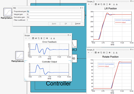
- Controller - Modeled as a closed loop PID controller using the controller library
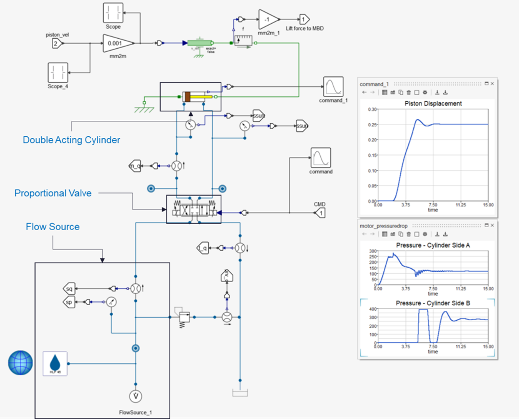
- Hydraulic - Modeled using Hydraulics by Fluid On library
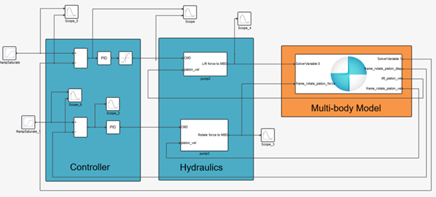
MODEL SETUP AND SIMULATION STEPS
- Commanded Signals - To enforce a prescribed motion for the system, signal generators (ramp saturate blocks) are used as inputs to all the PID systems. The motion is defined by the parameters of the ramp saturate block.
- Operations Analyzed - In this example, two different operations are prescribed in a sequential manner
- Guiding – lifts the roughneck and rotates to a commanded position
- Wrenching – turns the wrench to a commanded position
- Simulation – TA model acts as the master solver controlling the time stepping for both the system model and the MBD model.
RESULTS
The simulation can be used to analyze various aspects of the design for the specified operations -
Structural
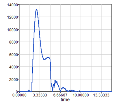
One can analyze the loads experienced by the components for a given operation (guiding illustrated here). These loads can be further used in a Finite Element Analysis (FEA, this analysis not covered in this article) of the component to understand the behavior (stress, strain) of the component.
Once the model is run, there are various ways to visualize the results. One can use HyperView to plot any saved outputs from .plt file. The MBD simulation (without hydraulic control system) can tell us about the forces experienced by all the components in the system under various loading conditions.
The plot shown below illustrates the loads on the actuators responsible for the lift and rotate motions.
Hydraulics & Control
By coupling the MV MBD simulation to a hydraulic and control system in TA, one can create a comprehensive digital twin for the system. Such a digital twin enables study of key design aspects like - the controller gains for a smooth and safe operation, the right size for the hydraulic components.
In TA, one can parameterize the controller gains to enable tuning. This can be done through an automated approach using the built-in optimization algorithms or a manual heuristic approach.
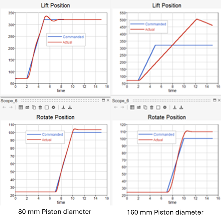
The results (shown below for a full system simulation using the scope blocks) show the commanded vs actual displacements of the actuators for lift and rotate motions with manually tuned controller gains.
One can also add a hydraulic circuit with various components (valves, pumps, actuators) to size them appropriately based on the full system behavior.
For example, one can explore different piston sizes for the lift actuator to see their effect on the performance of the full system. The plot below shows when the piston size is too large (160mm) the system is slow to respond, and overshoots compared to a smaller piston diameter of 80 mm. Studies like these are important when designing for safety to limit the movement of the system especially when humans are in the loop.
In addition, a digital twin also enables monitoring of power consumption of the hydraulic system. This is important to analyze for efficiency considerations. For example, one can use this information to choose the most efficient pump based on the operations.
CONCLUSION
This article demonstrates how a combined Multibody Dynamics (MBD) model in Motion View (MV) and a hydraulic control system in Twin Activate (TA) provide a comprehensive simulation platform for the design and analysis of iron roughnecks. By accurately modeling structural loads, optimizing hydraulic system performance, and tuning control gains through co-simulation, engineers can ensure the safety, efficiency, and robustness of these critical oil and gas industry devices. This integrated simulation approach allows for a deeper understanding of complex system behaviors under various operating conditions, ultimately leading to more informed design decisions and enhanced product development.
AUTHORS
Dheeraj Vemula, Technical Specialist
Ed Wettlaufer, Senior Technical Specialist
Chris Fadanelli, Solution Engineer - Systems Integration
CAD model credits – Taras K.
