
Technical Guide: Brake Noise Simulation Using Contact-Enhanced Flexible Multibody
Introduction
This guide outlines the process of conducting brake noise simulations using contact-enhanced flexible multibody simulation. The methodology focuses on accurately capturing transient friction-induced vibrations that contribute to brake noise, offering insights into model setup, execution, and analysis.
Simulation Approaches
Three primary methods are used for brake noise modeling, each with its own advantages and limitations:
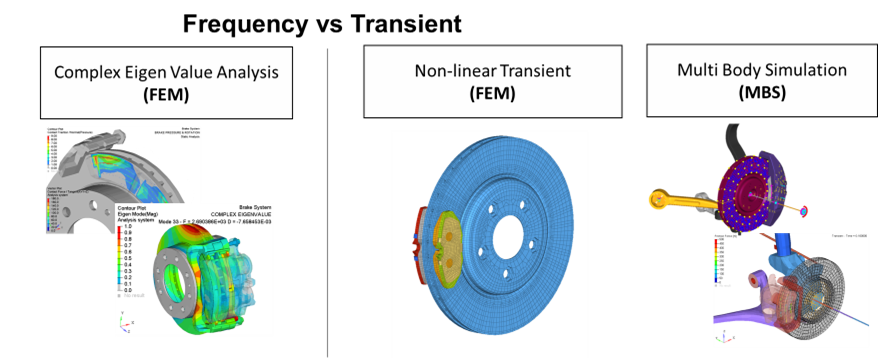
- Complex Eigenvalue Analysis (FEM): A frequency-domain approach offering fast results but requiring frequency-reduced models, making test correlation difficult.
- Non-Linear Transient Finite Element Analysis (FEM): Highly accurate but computationally expensive, often requiring significant simulation time.
- Multibody Simulation (MBS): Uses reduced-order flexbody models for faster simulations but struggles with localized deformations. Recent software improvements have enhanced accuracy and simplified the setup.
Simulation Setup
Setting up a brake noise simulation involves several key steps:
Model Preparation
Flexible multibody models of brake system components are created using the finite element solver OptiStruct. These reduced-order models (ROMs) capture dynamic behavior using Component Mode Synthesis (CMS). Pre-processing can be done with tools like HyperMesh or SimLab, but model reduction must be performed in OptiStruct to ensure MotionSolve compatibility.


Contact Definition
Accurate contact modeling is essential for simulating the stick-slip phenomena that drive brake noise. MotionSolve automatically manages flexbody-to-flexbody contact interactions, requiring only user-defined contact parameters in MotionView. Flex-to-flex Contact stiffness must be sufficiently high to ensure realistic deformation without interference from the contact elements themselves.


System Parameter Configuration
System stiffness influences vibration frequency, while damping affects amplitude. Proper calibration of these parameters allows the simulation model to align with laboratory dynamometer test results.
Simulation Execution
The execution process consists of:
- Running dynamic simulations in a multibody solver with predefined brake disk motion and brake pad pressure forces to replicate dynamometer tests.
- Varying damping and stiffness levels to evaluate their impact on noise generation. Increased stiffness leads to higher frequency vibrations, while damping influences the onset/offset of stick-slip events.
- Analyzing contact dynamics between brake pads and disks using the Altair Craig-Chang-Contact CMS method (CCC). This enhances accuracy by incorporating asymmetric mode shapes derived from predictive runs.
Advanced Techniques for Enhanced Accuracy
Craig-Chang-Contact (CCC) Method
This approach refines CMS by incorporating asymmetric deformation modes obtained from a predictive run. These modes improve the accuracy of contact pressure and local deformations.

Predictive Runs for Contact Footprint
Initial predictive runs capture contact forces, which are then used to refine the flexbody modes. This process ensures alignment between the flexbody's deformability and the observed contact footprint. (left) standard CMS, (right) enhanced CCC-CMS.

Analysis and Results
Load Case and Data Sampling
A standardized dynamometer load case was applied: 15-bar brake pressure on a stationary disk, followed by rotational acceleration at 1 rad/s². Data was sampled at 25 kHz to capture high-frequency noise sources.

System Stiffness Impact
To evaluate system stiffness effects, simulations were conducted on four brake system configurations:

- Brake disc and pads only
- Caliper and pistons added
- Knuckle added
- Full quarter-suspension system
Each configuration revealed how structural additions influence brake noise characteristics, emphasizing the need for a complete model.
Vibration Patterns and Frequencies
Friction curve variations affected oscillation patterns, while contact stiffness and damping levels influenced frequency content. Lower damping (purple curve) extended oscillation duration, whereas added components altered the stiffness distribution and noise behavior.

Stick-Slip Events
Simulation results identified the onset and offset points of stick-slip oscillations, key contributors to brake noise. By tuning simulation parameters, the model can be aligned with test bench data for improved predictive accuracy. Below is an acceleration and retardation tests of the Caliper model

Computational Performance
Multibody simulations were efficiently executed using enhanced flexbody representations. Computational time varied depending on the model complexity:
Model | DOFs | End Time | CPU Time (High / Low damping) @8cpu |
|---|
Brake disc and pads only | 869 | 1.0s | 13min / 22min |
Caliper & Pistons | 948 | 1.0s | 1h14min / 1h34min |
Knuckle Added | 993 | 1.2s | 1h12min / 3h5min |
Full Quarter-Suspension | 1107 | 1.6s | 3h / 3h44min |
These results demonstrate the feasibility of using multibody simulation for iterative design and optimization.
Conclusion
Contact-enhanced flexible multibody simulation provides an efficient and accurate approach for analyzing brake noise by capturing transient friction-induced vibrations. This method bridges the gap between finite element and multibody simulations, offering a computationally effective alternative.
By leveraging high-fidelity transient models, engineers can fine-tune critical parameters—such as damping, friction curves, and contact stiffness—to match dynamometer test results. The inclusion of additional structural components highlights the impact of system stiffness on brake noise characteristics, emphasizing the need for comprehensive modeling.
Future advancements will focus on refining friction models and enhancing contact definitions to further improve simulation fidelity, leading to better noise mitigation strategies in brake system design.
Linkes to content
MotionView model files (13.1GB): MotionView model files.zip
Simlab Flexbody fem files (123Mb): Simlab Flexbody Fem.zip
Technical Guide - Full document:
Presentation Slides:

