Overview

INTRODUCTION
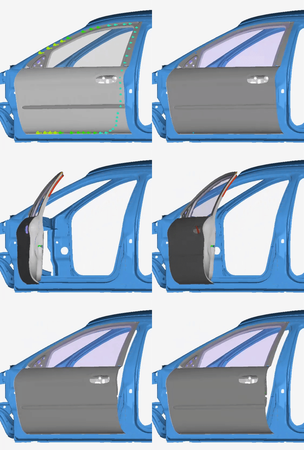
This study presents a CAE multibody dynamics simulation of a car door slam event, focusing on detailed kinematic models of hinges, latches, and sliders. The simulation evaluates dynamic constraints, structural integrity under impact, and stress distribution considering material properties. This virtual prototype could also be extended to aid automotive closures engineers in enhancing power window mechanisms, central locking systems, and sensor integration efficiency, reducing reliance on physical testing.
Opening and closing the door should require minimal user effort. The door also needs to survive many thousands of cycles and large impacts. Multibody simulation can be utilized to analyze the performance of a car door to ensure design goals are met.
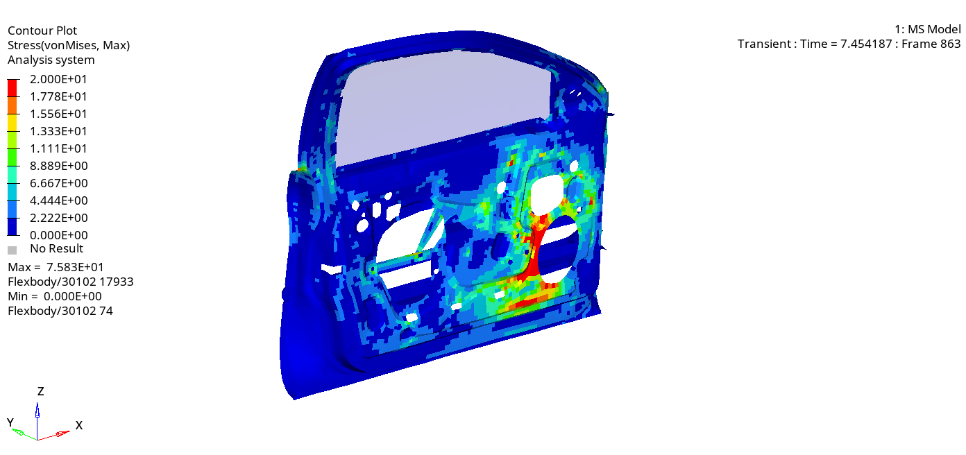
In this example, a car door slam is simulated in Altair’s MotionView and MotionSolve in order to analyze stresses and locate hotspots. The model accounts for the latch, door check strap, door cushions, and seal rubber to provide a comprehensive simulation.
Understanding the Model Definition in MotionView

Overall Multibody Dynamics Model
The model consists of a vehicle’s frame and a car door attached by two hinges. Inside the car door is a latch and a check strap. The latch mechanism, picture below, consists of two cams with torsion springs. Contacts are built between the cams and the striker. The striker is attached to the vehicle frame while the latch moves with the vehicle. The model also contains a simplified check strap, shown below. The cylinders are pushed into the check strap with springs. As the door swings outward, the check strap translates past the cylinders. The forces between the cylinder and check strap add extra resistance that the passenger must overcome when opening and closing the door.


Latch (Left) and Check Strap (Right)
The car door is modeled with two cushion forces. The forces are treated as impacts dependent on door position, velocity, contact stiffness, and contact penetration. The seal around the car door is modeled using forces as well. Markers attached to the door and frame are used to calculate the distance the seal is deformed. Forces are then computed based on the distance between the markers using curves for stiffness and damping interpolated from data points.

Stiffness force on the y-axis (N); Marker displacement on the x-axis (mm).
There are two simulations to perform after setting up the critical interactions between all components. First, a simulation will be used to compute the necessary force to open the door. Then, a second simulation will capture the door slam where stresses and hotspots can be analyzed. In both simulations, in the first 0.5 seconds the latch releases allowing the door to open.
For the opening force estimation simulation, a sensor input sensor output controller (SISO) will be used to calculate the door opening force. The controller will use PID control to open the door 80 degrees at a constant angular velocity in 2.5 seconds. The door angle acts as the process variable and setpoint. The force applied to the door is the output which can be extracted as a curve.
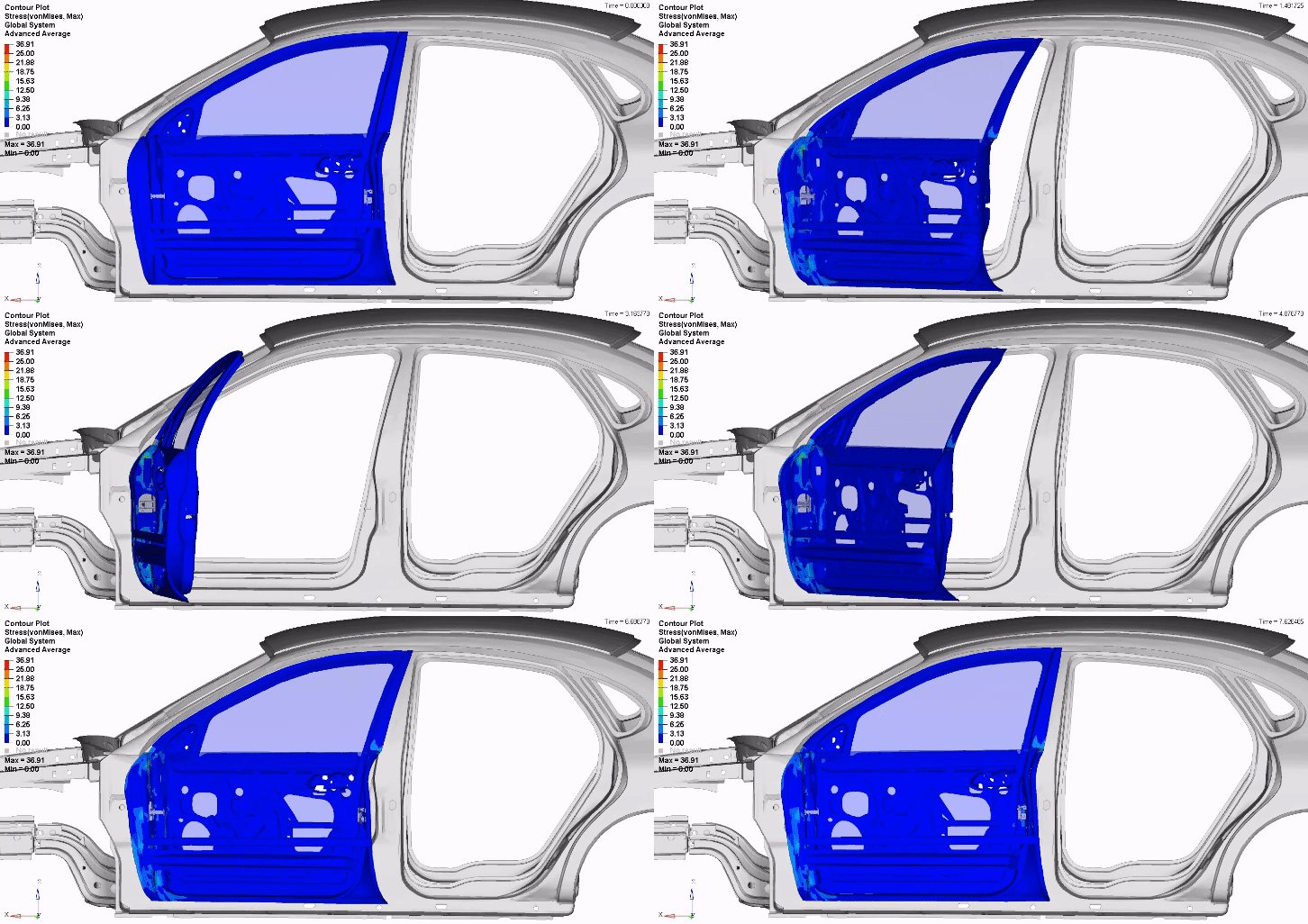
After extracting a force curve from the first simulation, a second simulation will open the door using the opening force curve and then apply a slamming force. The door will be a flexible body allowing the computation of displacements, strains, and stresses.
Pre-Requisite
SOFTWARE REQUIREMENTS
MotionView (2024 or newer)
MotionSolve (2024 or newer)
MODEL FILES
Door_Slam_Model.zip [Click Here]
Usage/Installation Instructions
MODEL SETUP & SIMULATION STEPS
Opening Force Estimation Model
- Open Opening_Force_Estimation_archive.mdl in MotionView.
- Run the analysis with an appropriate output directory.
- Open the h3d output file in HyperView to review the results.
Door Slam Model
- Open Door_Slam_Model _archive.mdl in MotionView.
- Run the analysis with an appropriate output directory.
- Open the h3d output file in HyperView to review the results.
Post-Requisite
RESULTS
After running the analysis and reviewing the results, additional data can be plotted in the HyperGraph client. The plot below depicts the required opening force vs time and opening force vs angle. The plots are similar because the door was opened at a constant angular velocity with a PID controller. The positive direction indicates a force pushing the door closed while the negative direction indicates a force pulling the door open. Initially the forces from the seal and cushions push the door open. A force against the door is required to maintain a constant velocity. Once the door is partially open, the cushions and seal no longer have an effect requiring the passenger to pull open the door.

Required Force over Time to Open the Car Door

Required Force to Open the Car Door as a Function of Angle
The required force curves are used to inform the motion of the door slam simulation. An 8 Newton force for 0.5 seconds is added to simulate the slamming force.

Passenger Force Input for the Door Slam Simulation

Door Motion and Seal Contact Forces

Latch Mechanism Contact Forces

Check Strap Contact Forces

Door Von Mises Stresses

Door Stress Hotspots
CONCLUSION
Multibody dynamics is a powerful tool allowing for the visualization of motion, forces, and stresses. In this example, we created a multibody model of a car door with a latch, check strap, cushions, and a seal. In one simulation, we used a sensor input sensor output (SISO) to find the required force to open the door. In a second simulation, we performed a door slam with a flexible body door to take into account the deformation of the door during the slam. During post-processing, we were able to review contact forces, door stresses, and identify hotspots.
AUTHORS
John Dagg, Systems Engineering Intern
Chris Fadanelli, Solution Engineer - Systems Integration
Door Slam Model Zip