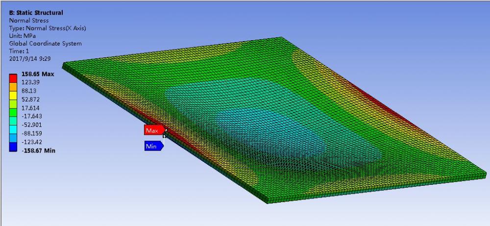
Why does OptiStruct result differ greatly from those of ANSYS?
Answers
-
Altair Forum User said:
Could you give me some help on my initial doubts? I'm really confused about that. From Ansys, we know that it use a second order element SOLID186 with full integration. How can we do this in OptiStruct? I want to know how this different result coming from.
Thank you in advance.
Roy
0 -
Altair Forum User said:
I saw the displacement results are similar, just stress is different. I think it is because stress is not output at outer position.
Enter panel analysis>control cards>GLOBAL OUTPUT REQUEST, slide down to activate 'STRESS' and select 'LOCATION' as 'ALL'
Run anaylysis again and open Hyperview>Contour> select stress result and activate 'Use corner data'
The max stress values are 133 and 143(XX) , I think they are comparable with ansys
Hi @tinh,
Could you show me some message about 'corner data'? From the help manual of HyperView, I only found following message. However, I don't think I have understood the meaning.
Roy
0 -
Hi,
when you do not use corner data => stress is value at element centroid => stress is constant in each element
when you use corner data => stress is interpolate from center to element corners => stress is varying in each element:
So when you use corner data => you got stress value at outer face of solid (interpolate), normally higher than at centroid of solid element
if you cover solid by membrane, you got more exact stress result. because stress at membrane elements does not need to be interpolated from centroid value
0 -
Altair Forum User said:
Hi,
...
when you use corner data => stress is interpolate from center to element corners => stress is varying in each element:
I think stress will be interpolated from integration points of each element, not from 'center'.
0 -
Yes,
sorry I am wrong.
and also the value at centroid is came from IP values, isn't it?
maybe solver output at center as default to save disk space
0 -
Hi Roy,
You can use shell elements with minimal thickness to simulate membrane effect.
It is normal that stress varies within element. So I think the centroid stress value is from the IP value
0 -
Altair Forum User said:
Yes,
sorry I am wrong.
and also the value at centroid is came from IP values, isn't it?
maybe solver output at center as default to save disk space
What if more than one integration points exist in one element? I think in this situation the stress in one element may be not constant.
In Ansys software, it also has nodal stress besides elemental stress. I don't know the stress in OptiStruct is elemental or nodal?
Roy
0 -
Altair Forum User said:
Hi Roy,
You can use shell elements with minimal thickness to simulate membrane effect.
It is normal that stress varies within element. So I think the centroid stress value is from the IP value
Hi Prakash,
However the shell nodes in optistruct have six degree of freedom which is not compatible with solid nodes only with 3 translational d.o.f.
Roy
0 -
Altair Forum User said:
Yes,
sorry I am wrong.
and also the value at centroid is came from IP values, isn't it?
maybe solver output at center as default to save disk space
I think 'centroid' value is just 'mean' value over Integration Points?
0 -
Altair Forum User said:
I think 'centroid' value is just 'mean' value over Integration Points?
I also want to know this. However, I have not found any information about this. For Ansys, it seems that the mean element stress is the average value of its nodes stress.
0 -
Hi Prakash,
How to define second order full integration solid elements in OptiStruct? Ansys use the second order SOLID186 element and I want to check it in OptiStruct.
In addition, could you explain what's the locking effect in solid?
Best Wishes
Roy
0 -
-
0
-
Altair Forum User said:
The stress results are exactly the same no matter how the ISOP parameter in PSOLID card values. Therefore, I don’t think the value of ISOP can change the element integration points. What’s more, from the manual of PSOLID card, the ISOP parameter is a special integration schemes for elasto-plastic nonlinear quasi-static analysis. But my example is a linear static analysis. So how to change the element integration point formulation in OptiStruct for linear static analysis? I think this is a fundamental set up for finite element analysis.
<?xml version="1.0" encoding="UTF-8"?>
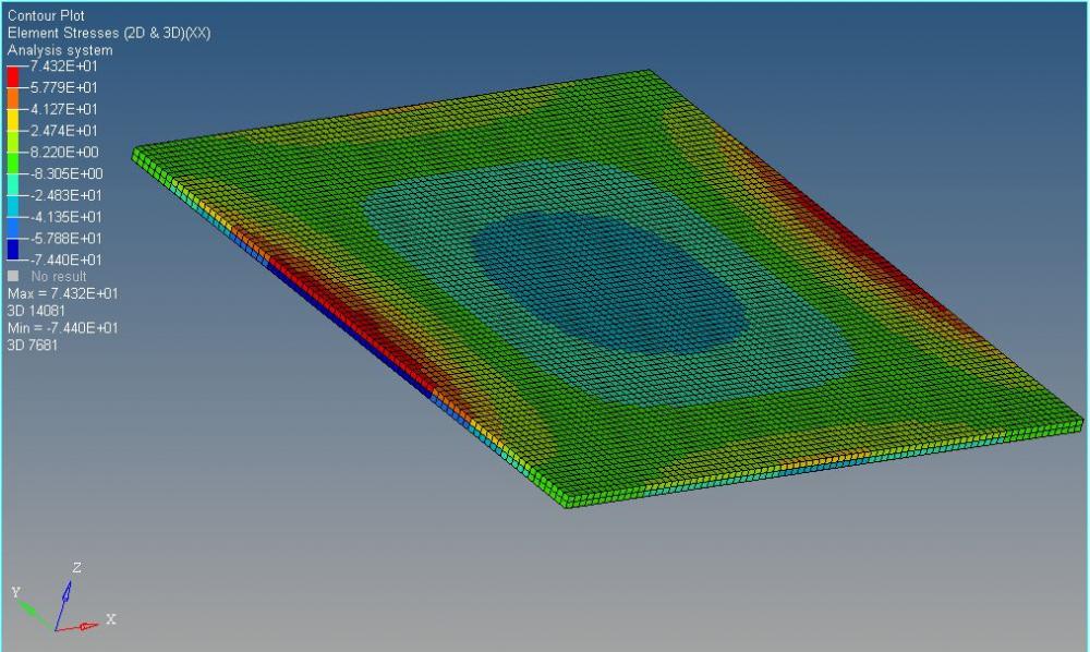
The model and the pdf file shows detail result.
Roy
0 -
Altair Forum User said:
Hi @Q.Nguyen-Dai,
It's strange I got a different result from yours. I have uploaded my model. The model came from your attachments, but I have change some parameter in skin pshell card because some errors. Could you show me how to set the right value to skin pshell card? Thank you.
0 -
Hi all,
From some test I found that the OptiStruct stress result is similar to Workbench element mean stress result (please see the attachments). So I suspect the stress output by OptiStruct may be element mean stress. One element mean stress means the average stress of all its nodes. For example, the element mean stress of a first order hexa element is the average stress of its 8 nodes which attached to the element.
<?xml version="1.0" encoding="UTF-8"?>
1. So does anyone can tell me which stress result had been output by OptiStruct?
2. How to output element integration point stress in OptiStruct? I think maybe the integration point stress should be compared since it had highest precision.
3. How many default integration points for different elements in OptiStruct? And how to change the integration points?
Best Wishes
Roy
0 -
@Roy Duan: Yes, I forgot to tell you modify pshell card for membrane behavior only.
Here's my used pshell card:
0 -
Altair Forum User said:
@Roy Duan: Yes, I forgot to tell you modify pshell card for membrane behavior only.
Here's my used pshell card:
<?xml version="1.0" encoding="UTF-8"?>
Hi @Q.Nguyen-Dai,
I have gotten the same result as you by setting the pshell card as you recommend. But how to verify this is a membrane element not a shell element? Thank you.
Roy
0 -
Hi all,
I am again with this topic because we talked about 'corner data' of stress
when I perform NLGEOM analysis, select GLOBAL_OUTPUT_REQUEST > stress > CORNER
but I don't see available corner data by Hyperview.
Is there any limited of this output request?
this is my *.fem file
0 -
Hi Tinh,
Conner stress data is not available for NLGEOM analysis type.
0 -
Thanks Prakash
Is there any specific reason ? I am supprise with this /emoticons/default_huh.png' title=':huh:' />
0 -
TInh,
I need to check about this. But what I know is because RADIOSS does not support.
Maybe you can try with NLSTAT with large displacement
0 -
Altair Forum User said:
This's special technique we use often with SAMCEF's solver to catch 'surface stress' of solid.
From solid mesh we extract the external faces and define them as a very small thickness (1.0E-5 mm) membrane.
Hi Mr Q.Nguyen
I have a doubt about above method although some documents also record that it may give more accurate result (altair's document said that, too).
Is it because SAMCEF does not output stress at grid points?
Optistruct can output stress at grid points (use card STRESS>LOCATION, or GPSTRESS)
and I saw those values is nearer to calculation than shell membrane stress, when i do a simple example
a round section bar, fixed one end and loaded on the other one.
- in beam model, stress (XX) is 10.19 (~calculation by c*M/I)
- in solid model, stress is 10.22
- in membrane shell, stress is 9.7
maybe, the method should not be applied in linear static analysis?
0 -
Maybe Optistruct does an 'extrapolation' from integration points?
0 -
Hi Prakash,
I tried modal analysis in Hyper mesh with Optistruct interface and in ANSYS workbench. I found very big difference in the natural frequencies. Can u help me through this??
0 -
Altair Forum User said:
Hi Prakash,
I tried modal analysis in Hyper mesh with Optistruct interface and in ANSYS workbench. I found very big difference in the natural frequencies. Can u help me through this??
Optistruct is GOOD software.
ANSYS is GOOD software too.
So if you found 'very big difference', I'm sure you make 'very big mistake' /emoticons/default_smile.png' srcset='/emoticons/smile@2x.png 2x' title=':)' width='20' />
0 -
0
-
Thanks Nguyen-Dai for your valuable information.
I already know that something wrong input i have given. But i am unable to find the same. So i was just asking for the different possibilities of mistakes.
0 -
Altair Forum User said:
Sorry I cant share the result file as it is confidential. But i can share values of natural frequencies.
in Optistuct first natural frequency is 13.87 Hz
in ANSYS wb first natural frequency is 594 Hz
So can u plz tell me what are the possibilities of wrong input data??
0 -
Altair Forum User said:
in ANSYS wb first natural frequency is 594 Hz
Did you validate the result?
First, we need to investigate from which solver is the error is coming from.
WIth just results values, it is difficult to come to a conclusion.
0