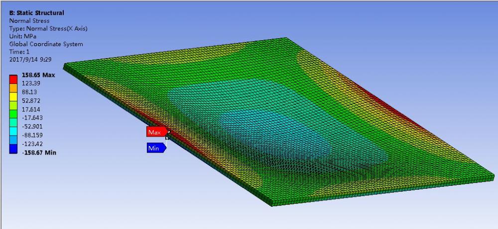
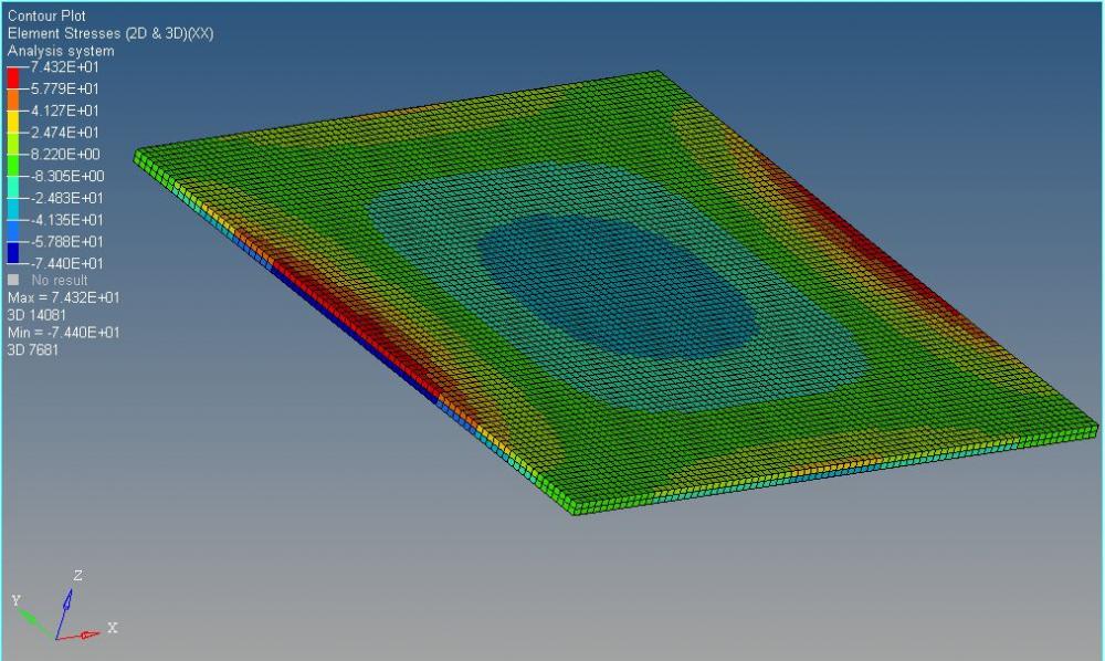
Why does OptiStruct result differ greatly from those of ANSYS?
Answers
-
Hi, for shell you have to select 'layer'
About averaging method , it is to unify results when they do not vary smoothy by element boundary. Refer to Hyperview help document
0 -
You said you use solid186 - 2nd order so in optistruct you have to use chexa20
In hpermesh enter 3d>order change>switch to 2nd
For intergration scheme, enter card editor of PSOLID ... but now I want to ask @Prakash that psolid card of OS does not have some fields as psolid card of NASTRAN, so i am not sure what the default intergration scheme in OS is. /emoticons/default_rolleyes.gif' title=':rolleyes:' />
0 -
Altair Forum User said:
Hi, for shell you have to select 'layer'
About averaging method , it is to unify results when they do not vary smoothy by element boundary. Refer to Hyperview help document
Hi tinh,
Z1, Z2 and Mid in the layer options means Top, Bottom and Middle surface? I can not find the help document about this hyperview postprocess graphics. Could you show me how to get it?
<?xml version="1.0" encoding="UTF-8"?>
Best Wishes
Roy
0 -
Altair Forum User said:
Hi Q.Nguyen-Dai,
What do you mean 'HEXA20 + Skin'? From the h3d file you uploaded, it seem that only shell elements existed.
Best Wishes
Roy
0 -
Hi all,
Besides the different results by solving solid model with OptiStruct or Ansys, I also find another problem about shell model in optistruct.
The pressure direction was in the negative Z direction, however I found the deformation of the shell model was in the positive direction. Anything wrong? I have uploaded my shell model.
0 -
Hi @Roy Duan I dont see this issue on 2017.2. Can you delete and recreate the pressure and check if this helps?
0 -
Altair Forum User said:
Hi @Roy Duan I dont see this issue on 2017.2. Can you delete and recreate the pressure and check if this helps?
Hi @Prakash Pagadala Do you get negative Z direction deformation by solving my model without anything modified? Is there any mistake about my defining method?
0 -
Hi @Prakash Pagadala, I think Ansys use SOLID186 element with full integration (SOLID186 is a second order element). How can I do this in OptiStruct?
0 -
Convert the elements to 2nd order in OptiSruct and try if you see similar results.
0 -
Altair Forum User said:
I have try my model with HW13 and HW14, the same similar error result were gotten. I found the main reason was that the fem file only support positive value no matter a positive or a negative value was defined in hypermesh. I suspect this may be a neglected mistake in hypermesh.
Could you try with other versions to solve the problem to see if similar results will get? Thank you.
Best Wishes
Roy
0 -
Altair Forum User said:
Hi Q.Nguyen-Dai,
What do you mean 'HEXA20 + Skin'? From the h3d file you uploaded, it seem that only shell elements existed.
Best Wishes
Roy
This's special technique we use often with SAMCEF's solver to catch 'surface stress' of solid.
From solid mesh we extract the external faces and define them as a very small thickness (1.0E-5 mm) membrane.
0 -
Roy Duan,
I see the same issue in HW 14.o Student Edition. But I deleted the ploads and recreated. Thie gave expected results
But this is strange. Graphics show load in -Z direction but results are reverse. I will check if this is already a known issues. If not I shall report the same to Dev team.
0 -
Altair Forum User said:
Roy Duan,
I see the same issue in HW 14.o Student Edition. But I deleted the ploads and recreated. Thie gave expected results
But this is strange. Graphics show load in -Z direction but results are reverse. I will check if this is already a known issues. If not I shall report the same to Dev team.
I checked the .fem file output by hypermesh. No matter positive or negative pressure value was defined in hypermesh, the pressure is positive in the output .fem file. I think this mistake results in the strange error result.
Best Wishes
Roy
0 -
-
Altair Forum User said:
Convert the elements to 2nd order in OptiSruct and try if you see similar results.
I try to convert the elements to 2nd order. But the results is similar to the first order, and it also differ from Ansys.
How to modify integration points? I cannot find the place to define it in hypermesh.
<?xml version="1.0" encoding="UTF-8"?>
Roy
0 -
Altair Forum User said:
You don't search it in HV help, do you? if you searched, you found it!
menu Help>Altair Help Home > in Hyperview help, open on browser tree Hyperview>Results>Contour Panel
or in 'search' tab, enter 'Z1 layer' to search
be not lazy with searching
0 -
Altair Forum User said:
Hi all,
Besides the different results by solving solid model with OptiStruct or Ansys, I also find another problem about shell model in optistruct.
The pressure direction was in the negative Z direction, however I found the deformation of the shell model was in the positive direction. Anything wrong? I have uploaded my shell model.
<?xml version="1.0" encoding="UTF-8"?><?xml version="1.0" encoding="UTF-8"?>
kindly search for PLOAD definition in OS: direction of PLOAD is calculated by right-hand rule (mean direction of shell normal)
in case you enter a negative value, the direction is inverted with shell normal
I guess your shell elems have normals as -Z (red face points to -Z)
so -0.2x{0 0 -1} = {0 0 0.2} , hypermesh will output 0.2 to *.fem file.
that why deflection is positive.
Nothing's wrong!
0 -
-
Altair Forum User said:
kindly search for PLOAD definition in OS: direction of PLOAD is calculated by right-hand rule (mean direction of shell normal)
in case you enter a negative value, the direction is inverted with shell normal
I guess your shell elems have normals as -Z (red face points to -Z)
so -0.2x{0 0 -1} = {0 0 0.2} , hypermesh will output 0.2 to *.fem file.
that why deflection is positive.
Nothing's wrong!
Hi @tinh,
I'd like to thank you for the HyperView help path and discussion about shell model problem.
I have checked my shell normal before. The normal is in the positive +Z direction. So I suspect the result. You can check it from the attachment model file.
I have tried with HW13 and HW14. Both give wrong result. According to @Prakash Pagadala, he got reasonable result by using HW2017.2
If you find something wrong with my model, please let me know. Thank you.
Roy
0 -
Hi @tinh and @Prakash Pagadala,
I defined the pressure load by selecting all shell elements.
At first, I have verified the shell normal before and it is in the +Z direction.
What's more, no matter the pressure value is set to 0.2 or -0.2, the deformation is the same (all to the positive direction). The attachment is my model file. You can check it. If you find something wrong, please inform me. Thank you.
Roy
0 -
Altair Forum User said:
This's special technique we use often with SAMCEF's solver to catch 'surface stress' of solid.
From solid mesh we extract the external faces and define them as a very small thickness (1.0E-5 mm) membrane.
Hi @Q.Nguyen-Dai,
Does the face shell elements have the same nodes with solid elements? The material of the shell elements is the same as solid, right?
Since solid and shell element has different D.O.F, how to understand the collection?
Roy
0 -
Altair Forum User said:
Hi @Q.Nguyen-Dai,
Does the face shell elements have the same nodes with solid elements? The material of the shell elements is the same as solid, right?
Since solid and shell element has different D.O.F, how to understand the collection?
Roy
Firstly, they're 'membrane' elements, not 'normal' shell ones. The nodes of membrane are shared the same as solid. They have the same material, but with very small thickness. The SAMCEF's membrane elements have 3 DoF each node, so that's compatible to Solid mesh.
0 -
Altair Forum User said:
Hi @tinh and @Prakash Pagadala,
I defined the pressure load by selecting all shell elements.
At first, I have verified the shell normal before and it is in the +Z direction.
What's more, no matter the pressure value is set to 0.2 or -0.2, the deformation is the same (all to the positive direction). The attachment is my model file. You can check it. If you find something wrong, please inform me. Thank you.
Can you reverse the normals and check?
I think it should work.
0 -
I checked it. It works if value is set by 'magnitude' but not 'x y z components'
It is due to hm, not OS
0 -
@tinh So you created pressure in normals directions?
0 -
I create pressure pload with z=0.2 then edit card of pload and see value 0.2
Then i recreate with z=-0.2 and edit card but still see value 0.2, it should be -0.2
When i use 'magnitude' instead of 'x y z' then the value in card editor changes sign when magnitude changes sign. This case hm did correctly.
Anyway we never need 'x y z' for pload because pload is always parallel to shell normal, just input value to magnitude is ok
0 -
Altair Forum User said:
Firstly, they're 'membrane' elements, not 'normal' shell ones. The nodes of membrane are shared the same as solid. They have the same material, but with very small thickness. The SAMCEF's membrane elements have 3 DoF each node, so that's compatible to Solid mesh.
Hi @Q.Nguyen-Dai,
That's a very useful technique. I want to ask Mr Prakash @Prakash Pagadala if OptiStruct has this special membrane element?
Thank you
Roy
0 -
Altair Forum User said:
I create pressure pload with z=0.2 then edit card of pload and see value 0.2
Then i recreate with z=-0.2 and edit card but still see value 0.2, it should be -0.2
When i use 'magnitude' instead of 'x y z' then the value in card editor changes sign when magnitude changes sign. This case hm did correctly.
Anyway we never need 'x y z' for pload because pload is always parallel to shell normal, just input value to magnitude is ok
Hi @tinh,
You are right. I have tried it with magnitude.
I found positive magnitude value is in the shell normal direction while negative magnitude value is in the opposite shell normal direction. This is different from other software. In many software, positive pressure magnitude directs in the opposite shell normal direction.
Roy
0