Tensile Test MAT25

Altair Forum User
Altair Forum User
Altair Employee
edited November 2020 in Community Q&A

Hello,


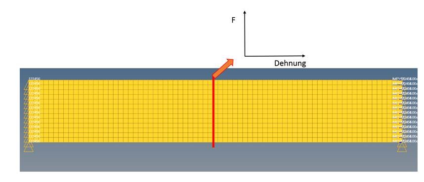
I'm trying to create a simple model of a tensile test for composite material. I have data from a real tensile test and i want to compare the data of the force/strain diagramm with the simulation model. To realise that i tried to read the output data of the nodes with the /TH/NODE card for die displacement and the /TH/SECT card for die forces. My problem is that i don't get any data for the forces in the T01 file. The Question is now: Is my defintion for the cross section incorrecton? 


Greetings 


Eugen

<?xml version="1.0" encoding="UTF-8"?>Force_Strain.jpg
Unable to find an attachment - read this blog

Tagged:

Answers

  • Altair Forum User
    Altair Forum User
    Altair Employee
    edited January 2017

    Hi Eugen,

    Please share the model file (_0000.rad) so that we can review the defined cross section.

  • Altair Forum User
    Altair Forum User
    Altair Employee
    edited November 2020

    Hello George,


    here is the .rad data.


    Unable to find an attachment - read this blog

  • Altair Forum User
    Altair Forum User
    Altair Employee
    edited January 2017

    Hi Eugen,

    The imposed velocity load is not assigned to any node groups. Please reassign the imposed velocity load and check.

  • Altair Forum User
    Altair Forum User
    Altair Employee
    edited November 2020

    Hello George,


    i fixed it, but still i dont get any results from the th/sectio outputblock. In the .out data there are only rows wtih 0 and it says that no nodes are connected to the section ( start at row 629, Im opening the files with the Programm Notepad++)

    Do I have to to set a GNODS for the definiton of the Crosssetction? 


    Unable to find an attachment - read this blog

  • Altair Forum User
    Altair Forum User
    Altair Employee
    edited November 2020

    Hi Eugen,

    There is no need to define GRNOD set also.

    Please find a simple model with a cross section defined.

    Unable to find an attachment - read this blog

  • Altair Forum User
    Altair Forum User
    Altair Employee
    edited November 2020

    Hello George,


    how you defined the Crosssection excatly? I tried it my self with an axe system wich i defined by nodes und a group of elements. But i still dont get any results. I looked in the output file and there a no nodes connected:


    Your Crosssection:

     SECTION         1 ID         1
     ---------------
            TYPE . . . . . . . . . . . . . . .         0
            FILENAME . . . . . . . . . . . . .                                                                                                                                                                                                                                                                                                                                                                                                                                                                                                                    
            DELTAT . . . . . . . . . . . . . .  0.000000000000    
            ALPHA. . . . . . . . . . . . . . .  0.000000000000    
            FRAME TYPE . . . . . . . . . . . .         0
            NUMBER OF INTERFACES . . . . . . .         0
            INTERFACES:


            NUMBER OF NODES. . . . . . . . . .        26
            NODES:
           450       447       419       451       458       284       459       500       497       501
           509       508       510       693       690       657       694       702       701       703
           747       744       748       756       755       757

            NUMBER OF BRICK ELEMENTS . . . . .         0
       BRICK      N1      N2      N3      N4     N5      N6      N7      N8

            NUMBER OF QUAD ELEMENTS . . . . .         0
       QUAD      N1      N2      N3      N4

            NUMBER OF SHELL ELEMENTS . . . . .        25
       SHELL      N1      N2      N3      N4
           161         1         0         0         1
           163         1         0         0         1
           164         1         0         0         1
           176         1         0         0         1
           178         1         0         0         1
           179         1         0         0         1
           226         1         0         0         1
           229         1         0         0         1
           241         1         0         0         1
           242         1         0         0         1
           245         1         0         0         1
           246         1         0         0         1
           436         1         0         0         1
           438         1         0         0         1
           439         1         0         0         1
           451         1         0         0         1
           455         1         0         0         1
           456         1         0         0         1
           506         1         0         0         1
           508         1         0         0         1
           509         1         0         0         1
           521         1         0         0         1
           522         1         0         0         1
           525         1         0         0         1
           526         1         0         0         1

            NUMBER OF TRUSS ELEMENTS . . . . .         0
       TRUSS      N1      N2

            NUMBER OF BEAM ELEMENTS . . . . .         0
       BEAM      N1      N2

            NUMBER OF SPRING ELEMENTS . . . . .       0
       SPRING      N1      N2

            NUMBER OF 3 NODES SHELL ELEMENTS .         0
       SHELL      N1      N2      N3


    ________________________________________________________________________________________


    My Crosssection:


     SECTION         2 ID         2
     ---------------
            TYPE . . . . . . . . . . . . . . .         0
            FILENAME . . . . . . . . . . . . .                                                                                                                                                                                                                                                                                                                                                                                                                                                                                                                    
            DELTAT . . . . . . . . . . . . . .  0.000000000000    
            ALPHA. . . . . . . . . . . . . . .  0.000000000000    
            FRAME TYPE . . . . . . . . . . . .         0
            NUMBER OF INTERFACES . . . . . . .         0
            INTERFACES:


            NUMBER OF NODES. . . . . . . . . .         0
            NODES:


            NUMBER OF BRICK ELEMENTS . . . . .         0
       BRICK      N1      N2      N3      N4     N5      N6      N7      N8

            NUMBER OF QUAD ELEMENTS . . . . .         0
       QUAD      N1      N2      N3      N4

            NUMBER OF SHELL ELEMENTS . . . . .         0
       SHELL      N1      N2      N3      N4

            NUMBER OF TRUSS ELEMENTS . . . . .         0
       TRUSS      N1      N2

            NUMBER OF BEAM ELEMENTS . . . . .         0
       BEAM      N1      N2

            NUMBER OF SPRING ELEMENTS . . . . .       0
       SPRING      N1      N2

            NUMBER OF 3 NODES SHELL ELEMENTS .         0
       SHELL      N1      N2      N3
     SUMMARY OF POSSIBLE INCOMPATIBLE KINEMATIC CONDITIONS :
     -----------------------------------------------------
                                      
     NO TRUE INCOMPATIBLE KINEMATIC CONDITION


    Unable to find an attachment - read this blog

  • Altair Forum User
    Altair Forum User
    Altair Employee
    edited January 2017

    Hi Eugen,

    Create an element set (/GRSHEL/SHEL) and recall the same in the grshel_ID option in crosssection card. In Frame_ID option, recall the system you have created.

    Please review the model I've sent before.

  • Altair Forum User
    Altair Forum User
    Altair Employee
    edited November 2020

    Hello George,


    after some adjustments on the model i finaly got a workin simulation with the data i want. But the results dont match with the real tests.

    Now i want to check if my inputs for the material data is incorrect or the mat law i choosed is not compatible. To do that i want to simplify the model. First to cut the elements to only 13 and set the same conditions before. The problems is that i get an error 760 and i dont know how to handle it. Here are the Error and the model file:

    Unable to find an attachment - read this blog

  • Altair Forum User
    Altair Forum User
    Altair Employee
    edited January 2017

    Hi Eugen,

    The component in the model is not assigned with any property or material. Assign Part card image to the component and assign the material and property and try running the analysis.

  • durukanbdilek
    durukanbdilek Altair Community Member
    edited November 2020

    I m sorry I have to realize tensile test analysis for cfrp composite specimen how to obtain load - displacement and stress - strain curve

    I modeled 1/4 of composite specimen  

    I uploaded .rad file 

    I dont know force output displacement output stress and strain output

    Unable to find an attachment - read this blog

  • Altair Forum User
    Altair Forum User
    Altair Employee
    edited November 2020

    Hi, 

    By creating time history output for elements it is possible to output stress and strain for the elements.

    Go to Analysis>Output Block> elements, select elements. Card edit the created output block and change the keyword accordingly. Use DEF keywprd to output the default outputs.

    Please go through the Help Menu on Output Blocks which describes about the various outputs available in Time History.

    Also please go through ths webiniat at https://www.youtube.com/watch?v=Ef7Spn-j7fA&list=PL1u26y75SCrA_BOCLaSewVCNY7xRvCTnA&index=6 which describes about creating output blocks.


    Using cross plot option you can crate load-displacement curves...etc. The steps for cross plotting is shown in an example file below. Please go through the documents attached.

    Unable to find an attachment - read this blog

  • durukanbdilek
    durukanbdilek Altair Community Member
    edited April 2017

    Hi, 

    By creating time history output for elements it is possible to output stress and strain for the elements.

    Go to Analysis>Output Block> elements, select elements. Card edit the created output block and change the keyword accordingly. Use DEF keywprd to output the default outputs.

    Please go through the Help Menu on Output Blocks which describes about the various outputs available in Time History.

    Also please go through ths webiniat at https://www.youtube.com/watch?v=Ef7Spn-j7fA&list=PL1u26y75SCrA_BOCLaSewVCNY7xRvCTnA&index=6 which describes about creating output blocks.


    Using cross plot option you can crate load-displacement curves...etc. The steps for cross plotting is shown in an example file below. Please go through the documents attached.

    in hypergraph, which file, I have to open? (.h3d, .out or t01) for plot

    Unable to find an attachment - read this blog

  • Altair Forum User
    Altair Forum User
    Altair Employee
    edited April 2017

    Hi,

    Open the T01 file in HyperGraph for plotting the curves.

  • durukanbdilek
    durukanbdilek Altair Community Member
    edited November 2020

    when I defined a crossection I recieve only force output but not stress, strain or displacement

    I want to recieve stress strain and displacement output how to realize?

    Unable to find an attachment - read this blog

  • Altair Forum User
    Altair Forum User
    Altair Employee
    edited April 2017

    Hi,

    I'm attaching a sample similar model where these options are used. I recommend you to go through the files.

    In HyperView we have an option, build plots panel which allows user to construct multiple curves. User has to select the required element and using this option plots can be created.


    Unable to find an attachment - read this blog

  • durukanbdilek
    durukanbdilek Altair Community Member
    edited April 2017

    in time history output for shell, F1 F2 variable are force or stress?

  • Altair Forum User
    Altair Forum User
    Altair Employee
    edited April 2017

    Hi,

    Please go through the Help Menu on /TH/SHEL which explains about Time History output variables for Shell Elements.

    <?xml version="1.0" encoding="UTF-8"?>Capture.PNG

  • durukanbdilek
    durukanbdilek Altair Community Member
    edited April 2017

    I have looked at this table however 

    when modelling of composite, I can obtain true stress in second direction (F2) why?

    how to define or change fiber direction ? 

  • Altair Forum User
    Altair Forum User
    Altair Employee
    edited April 2017

    Hi,

    Please go through Composite Properties topic in the Help Menu where different modeling methods for composites are explained, which includes defining plies where user can specify different material direction.

    <?xml version="1.0" encoding="UTF-8"?>Capture.PNG

  • durukanbdilek
    durukanbdilek Altair Community Member
    edited May 2017

    I cannot get strain data however I can stress data where stress datas are f1 or f2 right?

    how to get strain data?

  • Altair Forum User
    Altair Forum User
    Altair Employee
    edited May 2017

    Hi,

    You can input /ANIM/SHELL/TENS/STRAIN/N, where N is the layer number (eg:/ANIM/SHELL/TENS/STRAIN/1 for strain in layer 1), keyword in the engine file for extracting strain for each ply.

  • durukanbdilek
    durukanbdilek Altair Community Member
    edited May 2017

    ok, thanks 

    however  how to obtain strain data for HYPERGRAPH

  • Altair Forum User
    Altair Forum User
    Altair Employee
    edited May 2017

    Hi,

    You can create an output block for the elements and the time history output include plastic strains, strain rate...etc

  • Karthic_22061
    Karthic_22061 Altair Community Member
    edited June 2017

    Hi George,

    while defining the cross section.What is the  purpose of grnod_id (node group identifier), What these nodes do with results?

    <?xml version="1.0" encoding="UTF-8"?>Cross section.PNG

  • Altair Forum User
    Altair Forum User
    Altair Employee
    edited June 2017

    Hi Karthic,

    In HyperMesh, when crosssection is defined user has to create a set for the elements and also a node set which should be recalled here.

  • Karthic_22061
    Karthic_22061 Altair Community Member
    edited June 2017

    Hi George,


    set for the elements and also a node set which should be recalled here.

    So the node set contains the nodes that belong to the elements of element set?? I am correct


    And how to create System with FRAME/MOV, FRAME/MOV2 ????

    The system which i create is always FRAME/Fix by default. 

    so once when i select the system in /SECT, i am getting a message that ' Selected entity fails filter: Filter by system type/FRAME/MOV


  • Altair Forum User
    Altair Forum User
    Altair Employee
    edited June 2017

    Hi Karthic, 

    Yes Karthic, even I think you can create the section without creating node set.


    For FRAME/MOV, select the card edit option and select the system created and select FRAME type option.


    <?xml version="1.0" encoding="UTF-8"?>frame.PNG


    <?xml version="1.0" encoding="UTF-8"?>framee.PNG

  • Karthic_22061
    Karthic_22061 Altair Community Member
    edited June 2017

    Thankyou George

  • Madhura
    Madhura Altair Community Member
    edited May 2019

    Hello,


    I actually had a question about the output requests of RADIOSS solver 2018. I want to see 1). the changes in the fiber orientation and 2). % Thinning as outputs after running stamping simulations using MAT LAW 25 and Stack Prop 51. Currently, I am unable to see these outputs in Hyperview 2017.3. I am aware that these results are solved for in case of MAT 58 which is a Fabric law but are these outputs not available in case of MAT 25? 
    Thanks in advance!

    <?xml version="1.0" encoding="UTF-8"?>Fiber_orientation.JPG

    <?xml version="1.0" encoding="UTF-8"?>Thinning.JPG