contact

Altair Forum User
Altair Forum User
Altair Employee
edited October 2020 in Community Q&A

Hello all!

What is the best way for contact interaction with small penetration?

But reaally, i don't see penetration penetration checker doesn't see this too.

but in post processor i have the spurious forces.

i have a manual-crash book. i have tried to use approaches from this book, but i have had fail.

if i do type 7 all settings default i will no contact interaction untill i have large displacement.

i need advice and approach!=)

thanks for help.
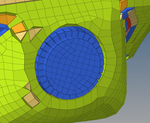
 

image.png.927b69c84c71c7787149a4a34e29ea3b.png

Unable to find an attachment - read this blog

Tagged:
«1

Answers

  • Simon Križnik
    Simon Križnik Altair Community Member
    edited August 2018

    Hi Mrt,


    if there are some parts initially in contact then initial penetrations should be modeled intentionally by setting:

    -Gapmin value bigger than physical thickness of the parts

    -Igap=1000

    -Inacti=5 or 6 (more on Initial Penetrations in the User Guide)


    Because the contact occurs at shell edges it is recommended to use type 11 line contact interface in addition (or type 19 which is a combined type 7 & 11). There is a Youtube video about contacts.


    Please note that initial penetrations are difficult to run with time step controls (CST or AMS) because timestep drops drastically if simulation increases penetrations beyond initial penetrations handled by Inacti flag.


    Unable to find an attachment - read this blog

  • Altair Forum User
    Altair Forum User
    Altair Employee
    edited August 2018

    Hi, @Ivan!

    i took this way:

    1. have remeshed properly my part

    2. have used type 7, Igap=1000

    3 Gap min=1.5 (it's value of housing half thickness)

    i don't see forces in first output frames.

    What do you think about my settings?

  • Altair Forum User
    Altair Forum User
    Altair Employee
    edited August 2018

    HI,

    if Igap is set to 1000, then the constant gap (min, equal to GAPmin) is used. Which is good most of the times. 


    If you still find any issue during post-processing try with variable gap by setting Igap to 3

  • Altair Forum User
    Altair Forum User
    Altair Employee
    edited August 2018

    @Prakash Pagadala, @Ivan.

    Solution has crashed with my settings.

    I'm reading reference_guide about interaction. i don't understand-if i have edge and surface with real gap X. why should i specify gap min and max? is gap max X and gap min t/2? is it called VARIABLE GAP? 

    so in my task edge to surface contact, but edge to surface is the same node to surface that is why i try to use type 7.


  • Altair Forum User
    Altair Forum User
    Altair Employee
    edited August 2018

    Hi,


    I will try with type 20 and I will see the results..

  • Altair Forum User
    Altair Forum User
    Altair Employee
    edited August 2018

    Hi,


    I will try with type 20 and I will see the results..

    my file is part of large model=)

    but large model would have crashed if i had used my settings.

  • Altair Forum User
    Altair Forum User
    Altair Employee
    edited August 2018

    is it right?

    i don't understand-if i have edge and surface with real gap X. why should i specify gap min and max? is gap max X and gap min t/2? is it called VARIABLE GAP? 

  • Simon Križnik
    Simon Križnik Altair Community Member
    edited August 2018

    Using the Gapmin value of 1.5 will not produce contact from the start of simulation because there is no initial penetration at this distance. Try to increase this value and check the resulting penetrations with tool > penetration check.


    Igap=1000 is a constant gap equal to Gapmin. It is more computationally efficient, but does no take into account the thickness of parts in contact

    Igap=1,2,3 are variable gap which is computed for each impact as the sum of the master element gap (gm) and the slave node gap (gs).


    If Igap=1, variable gap is computed as:
    max[Gapmin,(gs+gm)]max[Gapmin,(gs+gm)]
    If Igap=2, variable gap is computed as:
    max{Gapmin,min[Fscalegap(gs+gm),Gapmax]}max{Gapmin,min[Fscalegap⋅(gs+gm),Gapmax]}
    If Igap=3, variable gap is computed as:
    max{Gapmin,min[Fscalegap(gs+gm),%mesh_size(gs_l+gm_l),Gapmax]}max{Gapmin,min[Fscalegap⋅(gs+gm),%mesh_size⋅(gs_l+gm_l),Gapmax]}
     
    The problem with type 7 interface is it can't handle edge to edge contacts due to Edge to Edge Impact Locking (refer to User Guide). This is a possible reason why the computation crashes and it can be corrected with type 11 interface.
     
  • Altair Forum User
    Altair Forum User
    Altair Employee
    edited August 2018

    If you think the edge is more predominant try to use a edge to surface instead

  • Altair Forum User
    Altair Forum User
    Altair Employee
    edited August 2018

    Thanks all.

    i will try. i have never had a problem with contact issue in explct solver in my work=)

  • Altair Forum User
    Altair Forum User
    Altair Employee
    edited August 2018

    Yeah, guys, one more question! 

    How does density correlate with negative volume?

    i changed density (it was wrong by 1000 times!) and it is cause of analysis crashing=(

    i know about CFL)

    image.png.0487669fea698d4575cf4a4c60088f71.png

    Unable to find an attachment - read this blog

  • Altair Forum User
    Altair Forum User
    Altair Employee
    edited August 2018

    Not sure if the problem is the density at all. But looks like one or a few elements are undergoing large deformation.

    Can you check the element with ID 3318

  • Altair Forum User
    Altair Forum User
    Altair Employee
    edited August 2018

    Can you check the element with ID 3318

    it was good.

  • Altair Forum User
    Altair Forum User
    Altair Employee
    edited August 2018

    image.png.7d0533b035b60702139ef1b3ccc6898c.png

  • Altair Forum User
    Altair Forum User
    Altair Employee
    edited August 2018

    Well, the out file is showing negative volume for element 3318 (2nd engine out file)


    If you are using type 7 contact, can you set Gap min to zero 0 and let RADIOSS dertermines the minimal gap for the contact.

  • Altair Forum User
    Altair Forum User
    Altair Employee
    edited August 2018

    so for this part i use type_2 (tie_contact)

    it's interesting because in first model there density was larger it was all right=)

  • Altair Forum User
    Altair Forum User
    Altair Employee
    edited August 2018

    Can you try with Isolid 24?

  • Altair Forum User
    Altair Forum User
    Altair Employee
    edited August 2018

    i think about it.

    i use isolid 12 now. Is 24 better?

  • Altair Forum User
    Altair Forum User
    Altair Employee
    edited August 2018

    @Prakash Pagadala

    it hasn't helped=( 

    image.png.180504e7100cd3b2bac5e11489e70a7c.png


    maybe type_2 settings?

    image.png.1f03528b497338593052d3f7d35f013a.png

    but i have obtained intersting pic=)

    image.png.77200c758eecb374f51ecd3207c5791b.png

    image.png.ac07e574d5afaf036cdd4133f8dcc29c.png

  • Altair Forum User
    Altair Forum User
    Altair Employee
    edited August 2018

    can you share the updated model?

    Please use the file transfer link in my signature to share the model file
     

  • Altair Forum User
    Altair Forum User
    Altair Employee
    edited August 2018

    i'm sorry, i can not share total model.

    i'm trying to reproduce this error in simple part of model. if i do it i'll send you it.

    and could you give some advice?

  • Altair Forum User
    Altair Forum User
    Altair Employee
    edited August 2018

    @Mrt


    a couple of days ago I dealt with a similar error with type 2 and type 7 contacts.


    In that particular model, the user had the entire model in both master and slave on type 7


  • Altair Forum User
    Altair Forum User
    Altair Employee
    edited August 2018

    @Prakash Pagadala

    sorry, i don't understand what do you mean.=(

  • Altair Forum User
    Altair Forum User
    Altair Employee
    edited August 2018

    @Mrt The error will be the same but the problem maybe different. 

  • Altair Forum User
    Altair Forum User
    Altair Employee
    edited August 2018

    i think it's tie issue.

    everywhere is ok, except this area


    image.png.82cea2e47f0ce82ad159cc7980a64ffb.png<?xml version="1.0" encoding="UTF-8"?>image.thumb.png.c3f4da09ebf7c83dfe0267929db795c0.png

  • Altair Forum User
    Altair Forum User
    Altair Employee
    edited August 2018

    i think i have fixed it.

    cause is incompatible.

    2 wayes to solve these trouble

    -manually find conflict boundaries/tie

    -spotflag=25

  • Altair Forum User
    Altair Forum User
    Altair Employee
    edited August 2018

    but spotflag=25 decreases time step=( how to solve it?=)

  • Simon Križnik
    Simon Križnik Altair Community Member
    edited August 2018

    You could also use spotflag=27 or 28.


    I don't think there is a way to maintain the timestep with spotflag=25 as it is a penalty formulation- this means a spring is inserted which could lead to timestep drops.


  • Altair Forum User
    Altair Forum User
    Altair Employee
    edited August 2018

    Hi,


    Spotf= 25 is not recommended according to RADIOSS documentation and since it is a penalty formulation time step will be affected to get a convergence, 


    As @Ivan said you can try 27 or 28

  • Altair Forum User
    Altair Forum User
    Altair Employee
    edited November 2020

    Hi, @Ivan, @Prakash Pagadala!

    i seached interesting presentation yesterday.

    i tried with 28 and gts and only spotflag=28. but i've fogotten to create restart file=( and about result will write later=)

    p.s. did you have a some teoretical data about gts? so it inspires!

    image.png.7b216ed0d764b62138d02cb58597a24f.png

    Unable to find an attachment - read this blog