Non design space cone


<?xml version="1.0" encoding="UTF-8"?>
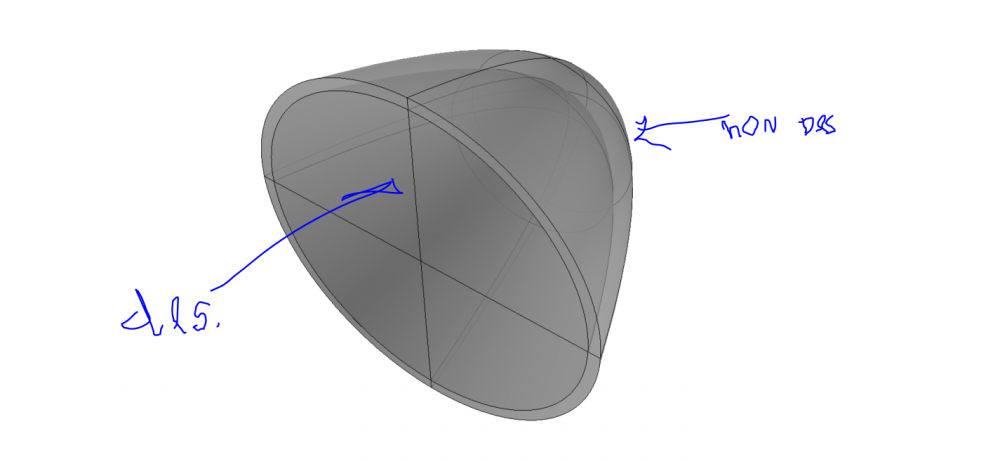
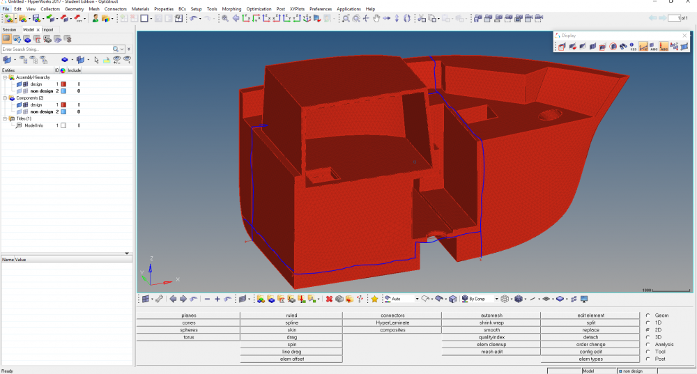
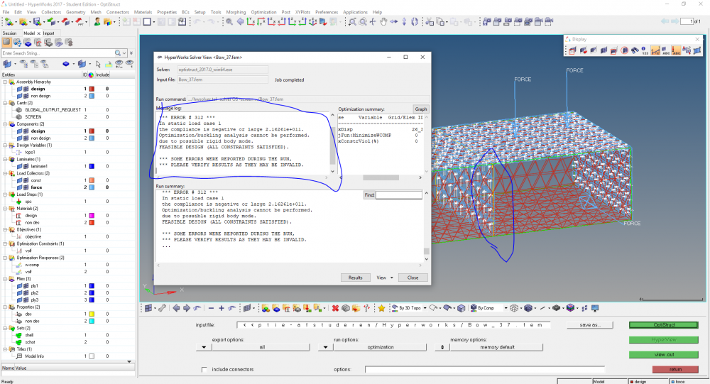
Hello, does anyone know how to select non design space for a cone? to perform topology optimisation.
It is a cone subjected to pressure.
And, is it also possible to model in CAD and select solids? Creating a component for non design space while having muliple solids does not work.
<?xml version="1.0" encoding="UTF-8"?>
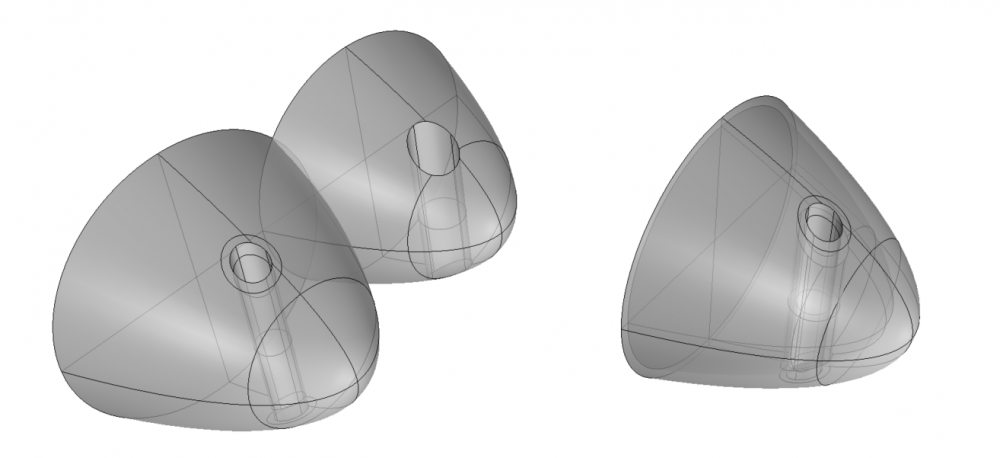
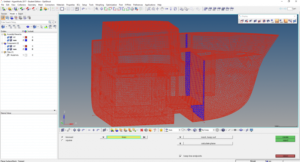
I also want to do this with openings included
Thanks in advance,
Find more posts tagged with


Hi,
I don't see a better way for this. I will check and come back to you soon.


Hello Prakash.
I think I will be able to manage by selecting the elements.
I have this other idea:
What would be the best way to make a shell plane for non design space, in the middle of a solid beam?
I tried making two different solids again but then the mesh will not correspond..
Any suggestion?
Best, thanks


Hi,
You can use 2D page>> Planes>> Square.
Select the three nodes of the plane N1, N2 and N3 and a base node and click apply (Mesh without surface) this should create 2D mesh in the plane.


Hello Prakash,
I want to split the solid and apply a meshed surface as shell elements for in non design space.
First selecting faces as you explained earlier is not an option.
Also 2D pages, Planes, Square does not help I guess..
Any idea?
Best


Hello Prakash,
I managed to made a meshed surface in non design space:
But I think this is not the proper method:
-I first trimmed the Solid with lines
-Then I performed planes > trimmed > lines as in the picture.
But now I don't think the elements/nodes from the mesh are connected with the mesh from the outer shell.
Any suggestion?
best regards,
Joep


Hi @Joep
Instead, trim the solid first and organize into different components.
You can use Solid edit with lines or nodes to trim the solid geometry.


Hello,
I tried to make a surface (ply surface) in the middle of a beam (this is a bulkhead within a composite ship), and it is in non-design space
I added forces on the outer face elements and on the middle surface
After analysis it seems the nodes on the faces are connected with the solid beam (design space) but the surface in the middle is not supported by the solid beam material:
I keep being unable to connect the middle surface. In previous posts you already explained the sequence but it seems even when I split the solids and organize into different components it does not work.
I want to organize the middle surface into non-design space, but since forces will be applied on this (composite) surface it should tranfer loads into the solid design space.
Any suggestion?
best regards,
Joep
<?xml version="1.0" encoding="UTF-8"?>


Due to the same problem I guess I receive this error:
Is it because there are unconnected edges?
If so, I do not understand how to obtain a: composite ply surface in non-design space in the middle of a solid beam element in design space
<?xml version="1.0" encoding="UTF-8"?>


I tried to make a surface (ply surface) in the middle of a beam (this is a bulkhead within a composite ship), and it is in non-design space
Hi, WHen you say in the middle of the beam, you mean you created in the middle of the component by extracting faces?
Hello Prakash,
Thanks a lot for the explanation and the video!
I think I managed, although I have this other problem.
I think it is quite easy when a straight face or rectangular shape should be shelled using your method.
But how can I do this for a curved part without manually selecting all the elements?
I have tried some ways but I dont manage.
<?xml version="1.0" encoding="UTF-8"?>
Here I managed to make a shell from the top face
But in the next picture I tried with a globe:
<?xml version="1.0" encoding="UTF-8"?>
Is there any way to do this faster? without manually selecting all the elements?
Since my final model will be a huge part with many nodes and elements..
Hope you can help me again!
Best regards,
Joep