Non design space cone

Altair Forum User
Altair Forum User
Altair Employee
edited October 2020 in Community Q&A

<?xml version="1.0" encoding="UTF-8"?>image.thumb.png.fbc02ce86e871679c2d4902d588b9c8d.png
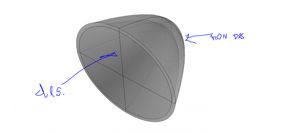
 

Hello, does anyone know how to select non design space for a cone? to perform topology optimisation.

It is a cone subjected to pressure.


And, is it also possible to model in CAD and select solids? Creating a component for non design space while having muliple solids does not work.

<?xml version="1.0" encoding="UTF-8"?>image.thumb.png.765d7c749ff284cde6d53146348e00a6.png
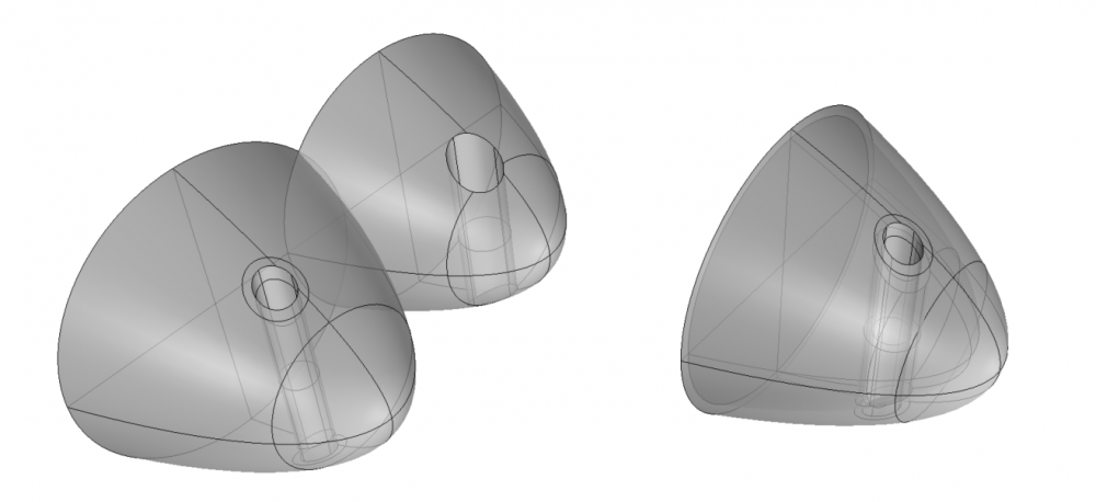
I also want to do this with openings included 


Thanks in advance,


«1

Answers

  • tinh
    tinh Altair Community Member
    edited March 2018

    Hi

    Try making a solid layer on cone's pressured surface and put it in non-design property

  • Altair Forum User
    Altair Forum User
    Altair Employee
    edited March 2018

    Two ways,


    as @tinh said, mesh and organize


    or Split the solid geometry and move into different components. 

  • Altair Forum User
    Altair Forum User
    Altair Employee
    edited March 2018

    Hello,


    Thanks for the reply. 

    Is it also possible to model both solids in my CAD software so I do not have to make or split solids in Hypermesh?


    Best regards,

  • tinh
    tinh Altair Community Member
    edited March 2018

    Hello,


    Thanks for the reply. 

    Is it also possible to model both solids in my CAD software so I do not have to make or split solids in Hypermesh?


    Best regards,

    Hi,

    Try it once, why not.

  • Altair Forum User
    Altair Forum User
    Altair Employee
    edited March 2018

    Hello, Thanks for the reply


    I tried this with different shapes:


    image.png.4ad6bf98fd1a864adbe61e05b6d7136c.png


    I made three solids in Rhino, and after importing in Hyperworks, I create a new component which I call 'non' for non design space.


    But, when organizing, I am not able to select solids.


    Best regards,


    Joep


    <?xml version="1.0" encoding="UTF-8"?>image.thumb.png.567c1b8dba5270bd0fabf0a95e269d7b.png

  • Altair Forum User
    Altair Forum User
    Altair Employee
    edited March 2018

    Hi,


    What type of file format is it?


    While importing, do you see something called 'Split components by the body'?


    If yes, use that to have different solids organized in different components. 

  • Altair Forum User
    Altair Forum User
    Altair Employee
    edited March 2018

    Hello,


    Thanks for the reply. The format is IGES.

    I see the option but I am not allowed to select it...


    image.png.c391e44137a0a7a97dceec5d37a4e441.png

  • Altair Forum User
    Altair Forum User
    Altair Employee
    edited March 2018

    Hi,


    One way is to import as it is, split the solid and organize into different components


    Other way is to try qith .stp or Parasolid format

  • Altair Forum User
    Altair Forum User
    Altair Employee
    edited March 2018

    Hello,


    Thanks for the reply.

    Since the model will consist out of many components the easiest and fastest way is to make the components in the CAD software.

    image.png.536b9ff6affa807bcd1d4832c162d482.png

    As the example above, is there a way to model the different components and then perform a quick split (with 1 button) to detach all individual components?

    Or is this only possible with Solid Edit - Trim with lines of planes or nodes?


    Best regards,


    Joep

  • Altair Forum User
    Altair Forum User
    Altair Employee
    edited March 2018

    Hi,


    Since HyperMesh is not a professional CAD tool, the available options are minimal. 

  • Altair Forum User
    Altair Forum User
    Altair Employee
    edited March 2018

    Hello,

    I still find it hard to believe it is not possible to use multiple components from the CAD program and perform analysis in this.


    I made this: consisting out of three different components.

    image.png.d4a45f5599838a941293865a3849ca50.png


    I saved this as STEP file and splitted the components in non-design and design space and applied loads and constraints:


    <?xml version="1.0" encoding="UTF-8"?>image.thumb.png.15ed3faa0aa5a5ae2ea594cabdea6384.png


    This results in ONLY displacement and stresses in the topside as shown in the picture. Is there any way to make the different components interfere?


    <?xml version="1.0" encoding="UTF-8"?>image.thumb.png.cb5f8a117448a0d3f21b04451b42730e.png


    I would very much appreciate your help!!


    Best regards,


    Joep


  • Altair Forum User
    Altair Forum User
    Altair Employee
    edited March 2018

    Hi @Joep


    Can you share the model file, please?

  • Altair Forum User
    Altair Forum User
    Altair Employee
    edited April 2018

    Hi @Joep


    There is no connection between design and non-design components. 


    I will share a file with you which has tie contact between both components. 


    In fact, I would suggest having the nodal connection if you are going for optimization.

  • Altair Forum User
    Altair Forum User
    Altair Employee
    edited April 2018

    Hello Prakash,


    Thanks again for the help. I have taken a better look at the file you made for nodal connection between different part from a STEP file:


    I have the following:


    -With an organic shape like the cone from previous posts it is hard to split an IGES file into separate components.

    -Since with IGES files it is not possible to organize different components I have to save and import my CAD files as STEP.

    -With STEP files I can organize different components (design and non design) but then there is no connection between the components.

    -Therefore it will be better to use STEP files, and perform  nodal connection (using SET, GROUP and CONTACT SURFACE) as you performed for me.


    Are these right assumptions? Really No other way to either organize IGES or split organic shapes?


    Because:

    I gave the beam as example, but the final model I am working on will have more solids to organize, and thus many more surfaces to manually perform a nodal connection onto.

    I think it will be quite extense as well to connect all these nodal connections.


    Thanks again!


    Best regards,


    Joep


  • Altair Forum User
    Altair Forum User
    Altair Employee
    edited November 2020

    Hi Joep,


    IGES should work. But not sure why it is not working for you.   Try the attached at your end and let me know if this works

    Unable to find an attachment - read this blog

  • Altair Forum User
    Altair Forum User
    Altair Employee
    edited April 2018

    Hello Prakash,


    Thanks for the reply.

    With your model is works, but these are surfaces:

    <?xml version="1.0" encoding="UTF-8"?>image.thumb.png.3713392fd0789b8fc634091760efd810.png

    With surface I produce myself it also works:

    <?xml version="1.0" encoding="UTF-8"?>image.thumb.png.b337a1a882b8241da6c169755664b7cf.png


    But with solids I produce it does not..

    <?xml version="1.0" encoding="UTF-8"?>image.thumb.png.b9ac50f0628ea68426b65d555c43d88e.png


    Maybe a setting when importing? Or, maybe I have to split the solids? with the option ''Do not merge edges'' it makes no difference.

    I shared the file with you.


    Best regards,


    Joep

  • Altair Forum User
    Altair Forum User
    Altair Employee
    edited April 2018

    Hi @Joep


    Do you have the native IGES.


    In the model you shared, I see surfaces only and no solids. 

  • Altair Forum User
    Altair Forum User
    Altair Employee
    edited April 2018

    Hello Prakash,

    I think I found it.


    Geom > SOlid > bounding box, then select all surfaces.


    Thanks,


    Best ragrds,


    Joep

  • Altair Forum User
    Altair Forum User
    Altair Employee
    edited April 2018

    Hello,


    I have tried some more complicated design/non-design spaces but it seems Hyperworks is not able to make proper solids out of it..


    I first save as IGES, import, > Geom > Solid > boundary box:

    image.png.b75b80f2d4df78db4b3bc3d2c07626eb.png


    Then I choose all surfaces.


    <?xml version="1.0" encoding="UTF-8"?>image.thumb.png.9465c58ac14298fdbe52a148a7e77406.png


    When I want to organize the created solids in design and non-design space not all surfaces have created a solid, I think because adjacent sufrace form connections with other surfaces.


    Should I:


    -connect all these surfaces into one in the CAD software?

    -combine the surfaces to solids in Hyperworks manually?


    best regards,


    Joep


  • Altair Forum User
    Altair Forum User
    Altair Employee
    edited April 2018

    Hi @Joep


    In order to form a solid, there has to be a closed volume of surfaces and from the picture, I see there are unbounded surfaces. 


  • Altair Forum User
    Altair Forum User
    Altair Employee
    edited April 2018


    -connect all these surfaces into one in the CAD software?

    -combine the surfaces to solids in Hyperworks manually?

    Whichever is convenient for you. 

  • Altair Forum User
    Altair Forum User
    Altair Employee
    edited April 2018

    Hello,


    Thanks for the previous help.

    There is this other challenge I am working on:


    I would like to perform a topology optimization onto a composite part. For this I have modelled a solid, and surfaces on the outside:

    (Since I am going to optimize a ship section)


    I put the yellow surfaces in a non-design component and assigned PSHELL (later I will assign orthotropic card)

    I put the red solid in a design component and assigned PSOLID (I will later also assign orthotropic card)


    After this I meshed the solid with tetramesh, volume tetra

    And I meshed the surfaces with 2D automesh.


    Then I applied constraints and loads. As you can see, the mesh nodes do not overlap.


    <?xml version="1.0" encoding="UTF-8"?>image.thumb.png.555615b8093a42940585ed4bc92ef4ae.png


    Any Idea how I would be able to combine a (composite) shell element in non design space with a solid element in design space for topology optimization?


    Best regards,


    Joep


    <?xml version="1.0" encoding="UTF-8"?>image.png

  • Altair Forum User
    Altair Forum User
    Altair Employee
    edited April 2018

    In other words:


    How can I perform a topology optimization on a solid, of which the outer surface not a solid but a composite ply is?


    Best regards,


    Joep

  • Altair Forum User
    Altair Forum User
    Altair Employee
    edited April 2018

    Hi Joep,


    Are both components connected?


    If not you can use the Edges (Shift+F3) panel to equivalence. 

  • Altair Forum User
    Altair Forum User
    Altair Employee
    edited April 2018

    Hello Prakash, Thanks for the reply.

    Do you mean connected edges?


    I think at the moment the solid is connnected in 1 component, while two unconnected surfaces are in component 2.

    <?xml version="1.0" encoding="UTF-8"?>image.thumb.png.b84b0f7cce87697d30fa4c420f4ff4f8.png


    Now I want to apply material properties and load cases so I can optimise the solid for topology.


    But, how do I mesh? Or should I connect the surfaces to the solid?

    Best regards,


    Joep

  • Altair Forum User
    Altair Forum User
    Altair Employee
    edited April 2018

    You can fill the box with solid elements and extract faces on the face of interest. This face should be connected to solid elements.


    Organize the Face elements (shell elements) to a different collector. 

  • Altair Forum User
    Altair Forum User
    Altair Employee
    edited April 2018

    Hello Prakash,


    Thanks for the quick reply.

    Is it also possible to model the solid and surfaces in CAD software?

    And then somehow connect the surfaces to the solid?

    Since it will be an organic an complicated ship section I would like to model this..


    Best regards,


    Joep

  • Altair Forum User
    Altair Forum User
    Altair Employee
    edited April 2018

    Is it also possible to model the solid and surfaces in CAD software?


    It MAYBE possible... 

  • Altair Forum User
    Altair Forum User
    Altair Employee
    edited April 2018

    Hello Prakash,


    I mean, the model in the picture is modelled in Rhinoceros, in which I made a solid and a surface.

    So importing this is possible.


    But I keep getting different meshes for both collectors and I cannot find anything to connect them in Hyperworks, and secondly, to perform a Solid Mesh + a Surface Mesh, so that the nodel overlap and connect.


    Or am I looking in the wrong direction?


    Best regards.


    Joep

  • Altair Forum User
    Altair Forum User
    Altair Employee
    edited November 2020

    @Joep


    You can use rigids or TIE contact to connect shell and solid elements. 


    I am also attaching a video on how to create face elements. 


    Unable to find an attachment - read this blog