🎉Community Raffle - Win $25

An exclusive raffle opportunity for active members like you! Complete your profile, answer questions and get your first accepted badge to enter the raffle.
Join and Win

Surface Continuity - A Comparison

User: "Altair Forum User"
Altair Employee
Updated by Altair Forum User

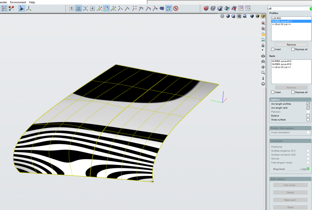
Can anyone explain to me why these two loft methods result in different surface geometry?

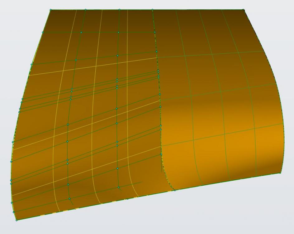
1. Loft curve 1 to curve 2 (with rails), Loft edge to curve 3 (same rails), adjust continuity to g2.

<?xml version="1.0" encoding="UTF-8"?>Evolve_SurfCont_2surf.thumb.JPG.4ce14c6a13c6629ad3f1224cce51b6f0.JPG

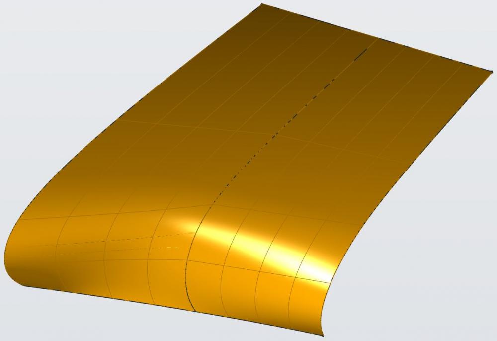
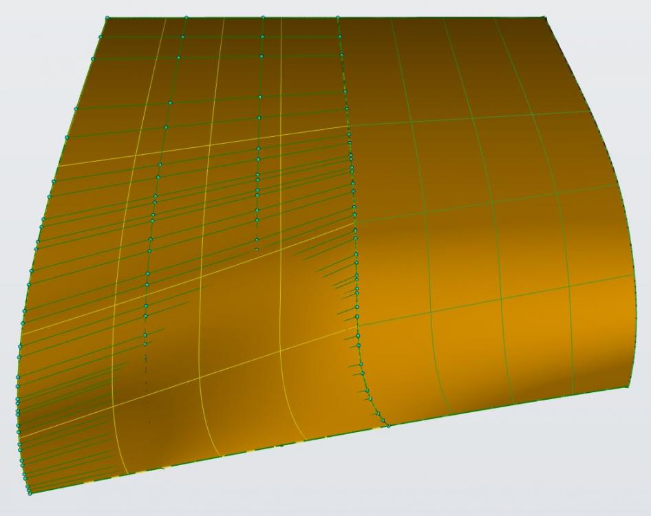
2. Loft curve 1 through curve 2 to curve 3 (with rails)

<?xml version="1.0" encoding="UTF-8"?>Evolve_SurfCont_1surf.thumb.JPG.cb70f821005624a15c47e08368d7ed5b.JPG

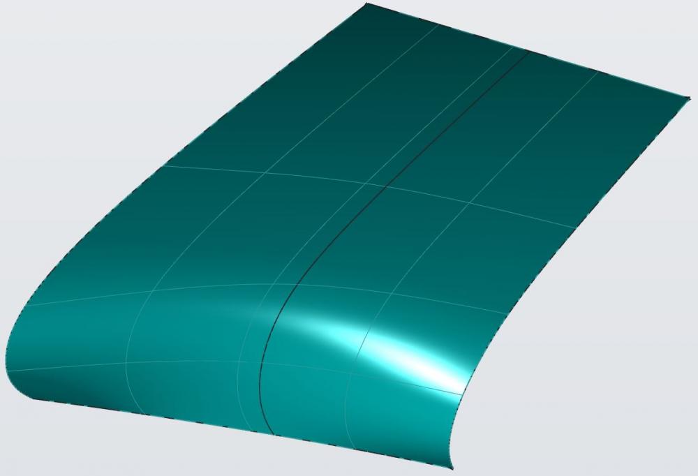
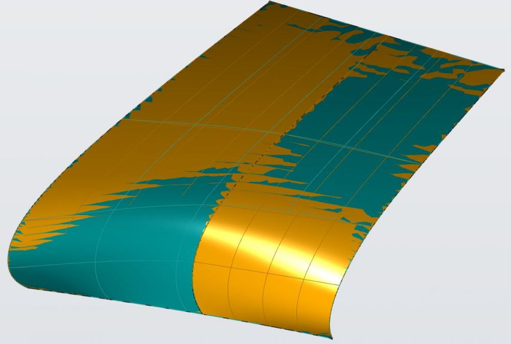
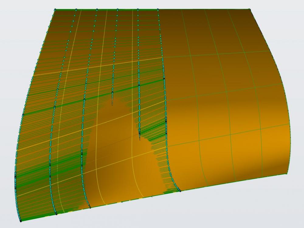
Resulting geometry is similar, but not quite.  It looks like the second method allows the isoparms to be evenly spaced across the entire surface, and therefore smoother overall.  Also notice the strange artifact on the left-hand side of method one.

<?xml version="1.0" encoding="UTF-8"?>Evolve_SurfCont_Comp.thumb.JPG.01e78eb357b3f2544a163d5815a20bc1.JPG

Find more posts tagged with

Sort by:
1 - 8 of 81
    User: "Altair Forum User"
    Altair Employee
    OP
    Updated by Altair Forum User

    I also noticed a drastic increase in hull lines when adjusting to G2 continuity.  Is that typical?

    Positional surface constraint:

    <?xml version="1.0" encoding="UTF-8"?>Evolve_SurfCont_Positional_hulls.thumb.JPG.e632261bcd11e8335e792b93f60d1399.JPG

    G1 Tangential surface constraint:

    <?xml version="1.0" encoding="UTF-8"?>Evolve_SurfCont_G1_hulls.thumb.JPG.fb90a6c31384832cec273454273279f8.JPG

    G2 Curvature surface constraint:

    <?xml version="1.0" encoding="UTF-8"?>Evolve_SurfCont_G2_hulls.thumb.JPG.0200bdd7927e082b36b0757f554a23e2.JPG

    User: "ArjunA_22390"
    Altair Employee
    Updated by ArjunA_22390

    Hi Steve,

    Please attach the source file. The differences are mostly due to curve properties. I can take a look at it.

    User: "Altair Forum User"
    Altair Employee
    OP
    Updated by Altair Forum User

    Thanks Arjun.  It is attached.

    Unable to find an attachment - read this blog

    User: "Altair Forum User"
    Altair Employee
    OP
    Updated by Altair Forum User

    Hi Steve, these two method are quite different since in the first you make a Loft without taking into consideration the last curve and getting a more straight shape, and then you make another Loft which is forced to take the edge of the first one as a reference for G2 continuity and so there is no way for it to modify the first Loft.
    This method generates for sure more points because of the higher level of constraints you are applying.

    The second is way lighter since you give all the curves from the beginning and you leave more freedom to the Loft tool to make a shape that better interpolate all the curves.
    You still get continuity in the middle, maybe even higher than G2, but that is an internal continuity (internal to the surface itself) that is way easier to achieve.

    You might get another variation by making the first Loft from curve 2 to curve 3, and then making another Loft with G2 continuity in the middle edge.
    This would be the same as the first one bit with a different shape, since you get the more flat part between curve 2 and 3, and then the more curved one after the continuity point.

    Hope this clarifies.

    Ciao!

    Antonio

    User: "Altair Forum User"
    Altair Employee
    OP
    Updated by Altair Forum User

    Thanks Antonio - that does help clarify.  For these three curves I would, of course, most easily get a nice surface by including all three.  I'm trying to understand what will happen when I start adding additional curves to represent what will become a significantly more complex shape and if the loft tool is the best method to move forward.  It's helpful to see that there's a difference between internal continuity of a surface and one applied after the fact by adjusting the edge constraint.

    User: "ArjunA_22390"
    Altair Employee
    Updated by ArjunA_22390

    Hi Steve,

    I took a look at your file. If you turn on the ' Arc length profiles' and 'Arc length rails' option, the issue should go away.

    <?xml version="1.0" encoding="UTF-8"?>for_steve.png

    User: "Altair Forum User"
    Altair Employee
    OP
    Updated by Altair Forum User

    Thanks again Arjun.  The surfaces are much closer with that method and it also eliminated the surface artifact I had observed.

    I understand that the arc length profiles and arc length rails options control how evenly the isoparms are spaced, but could you explain what this means?  Is it an alternate set of constraints or a secondary solution for the NURBS calculations?

    Thanks!

    User: "Altair Forum User"
    Altair Employee
    OP
    Updated by Altair Forum User

    Hi Steve,

    The Arc Lenght checkbox activates an internal reconstruction of the curves before to process them trough the Loft tool.

    It would be kind of the same if you would do that by hand on the curves and then apply the Loft tool.
    The advantage of having it as an option in the tool is that it is much faster and you can use it also on surface edges.

    Antonio