Composite Wing Free Size Optimization
Hello guys,
I'm working on my master thesis which is the structural optimization of a rear wing for a race car.
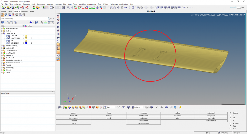
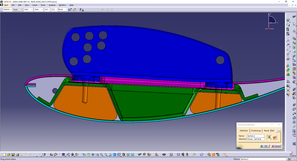
The wing is composed of 2 skins (top and lower) and one structural rib on the middle. All these parts are bonded together.
<?xml version="1.0" encoding="UTF-8"?>
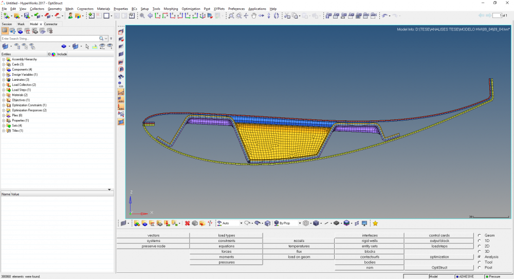
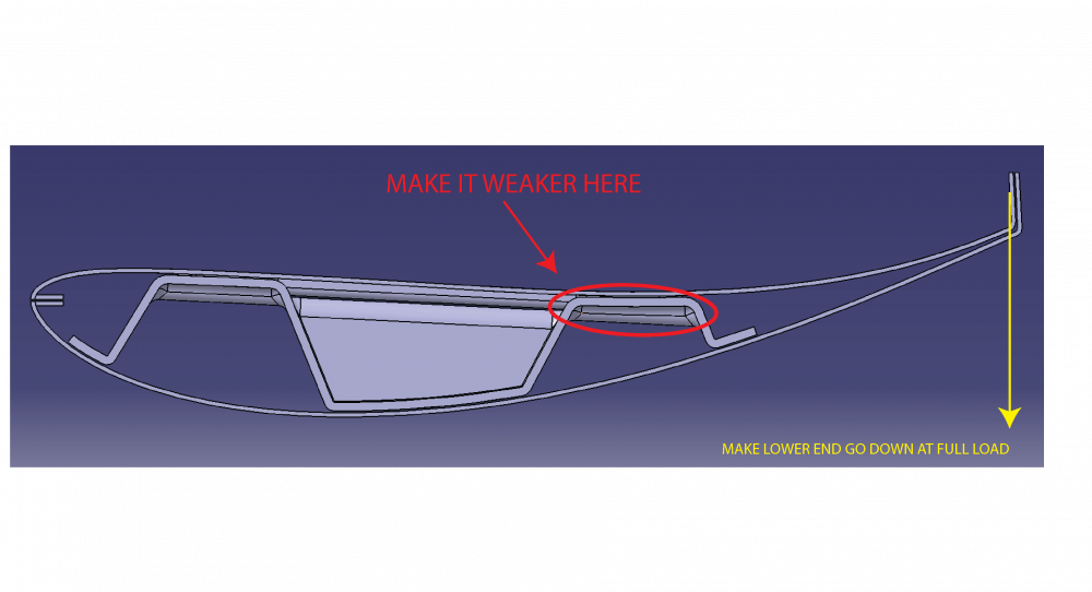
Here you can see the side view, the three elements of the wing with the standard lay up
<?xml version="1.0" encoding="UTF-8"?>
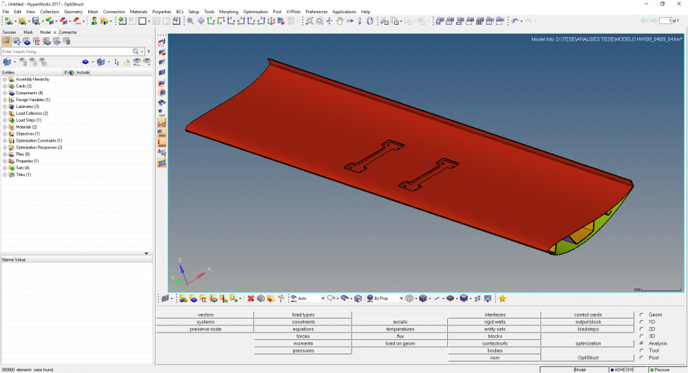
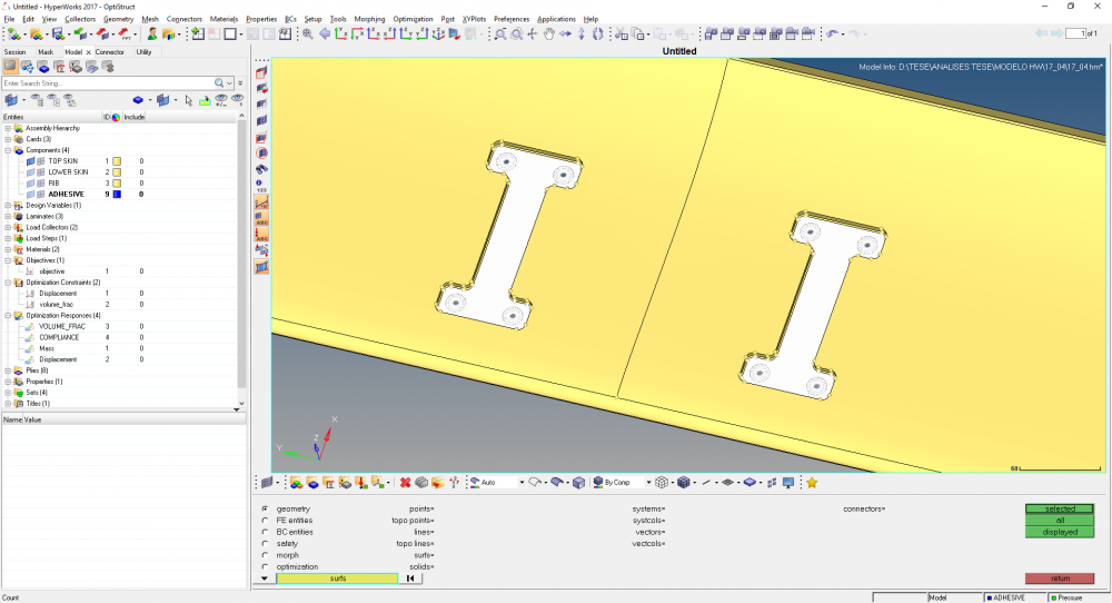
Here you can see the view from the Top
<?xml version="1.0" encoding="UTF-8"?>
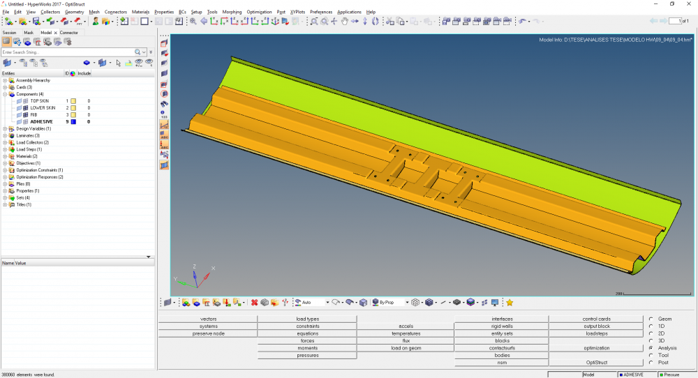
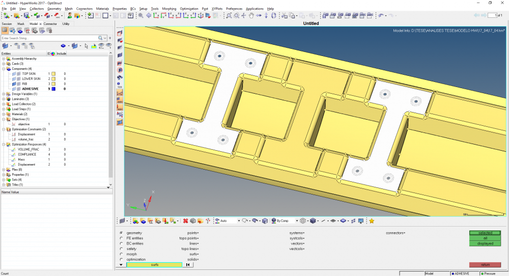
And in here you can see the rib.
I've modeled the connection between these elements with are connectors of the rigid type:
<?xml version="1.0" encoding="UTF-8"?>
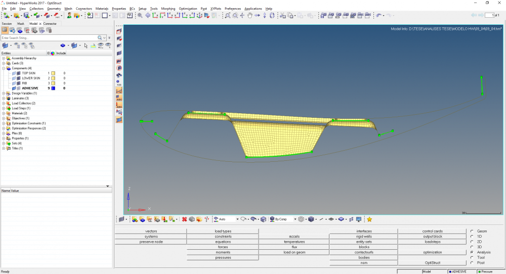
Connector as seen from the side.
<?xml version="1.0" encoding="UTF-8"?>
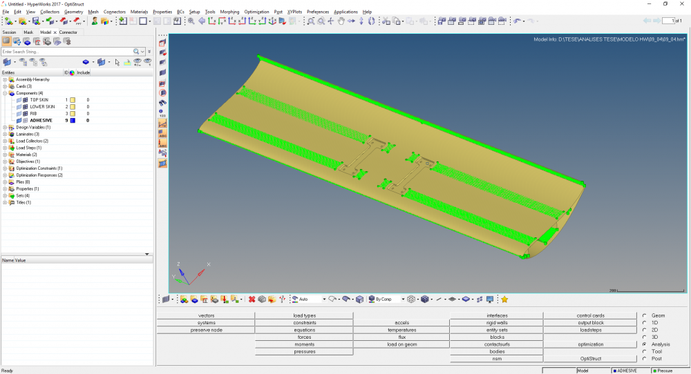
Connectors as seen from the top.
The wing is constrained on the middle on all 6 DOF:
<?xml version="1.0" encoding="UTF-8"?>
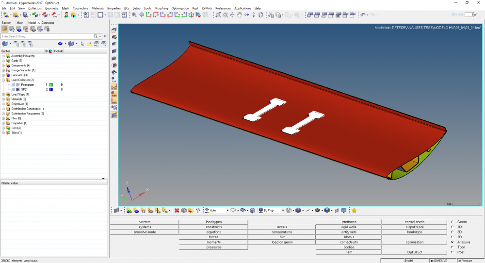
And on the rest of the top skin, a 400kg load is applied:
<?xml version="1.0" encoding="UTF-8"?>
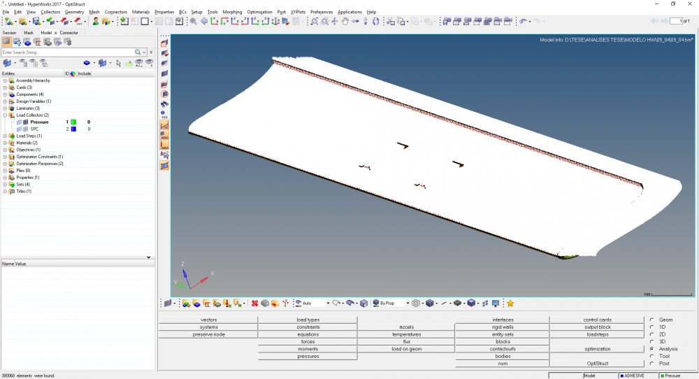
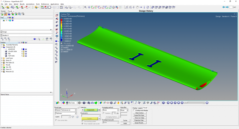
I've run the standard analysis and for the general lay up everything seems fine. The deformations, stresses and the failure criteria all sound plausible.
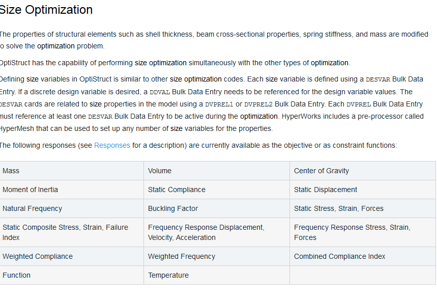
The thing is, when I try to run the first free size optimization a lot of weird things happen:
1 - It takes a LOT of time - for each iteration it takes 30min or more
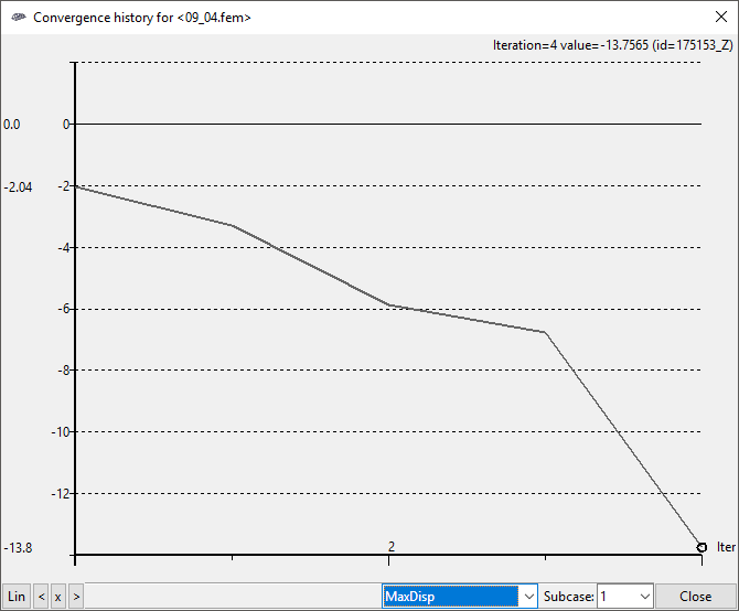
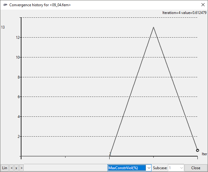
2 - It starts fine, but then it completely violates my constraints
3 - The % of constraint violation does not match
<?xml version="1.0" encoding="UTF-8"?>
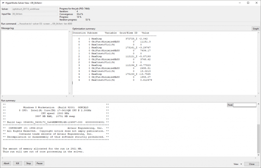
I think I've followed everything as it is supposed, but I'm not getting any decent results...
Can anybody help me?
Sorry for the long post...
Gonçalo Pimenta
PS - The plies shown above are for the general lay up (each ply with .66mm tchickness). For the analysis, I switched to 2mm. On the standard analysis I get 6mm maximum deformation on the wing and for the optimization my constraint is 6mm maximum displacement.
Find more posts tagged with
Hello @Prakash Pagadala,
Nice to ear from you!
<?xml version="1.0" encoding="UTF-8"?>
Do you mean that the most of displacement is happening is this area highlighted?
Also - you are suggesting I minimize compliance (objective) for a certain volume fraction right (dconstraint - the value of which I decide)?
Thank you very much!
Yeah, that's weird...
Because in reality, the nodes below the area that is fixed (SPC) are bonded (the rib is bonded to the top skin on that place).
In here I left them like that because Optistruct dind't like the SPC applied on areas with area connectors.
Can you confirm that the nodes you are seeing flying away are from the rib?
Also, do you think it makes sense that I also constrain (SPC) these nodes from the rib like I did with the ones on top of it?
<?xml version="1.0" encoding="UTF-8"?>
A - Nodes constrained on the Top Skin
<?xml version="1.0" encoding="UTF-8"?>
B - Area bonded to the area shown before (A) on real life. Do you think it makes sense to constrain these areas with SPC too?
Thanks!
The wing works like this:
<?xml version="1.0" encoding="UTF-8"?>7
The big blue part is attached to the pillar (double swan neck)
The parts on orange are aluminium inserts that are bonded inside the wing
The green part is the rib
The pink part is the top skin
The light blue part is the lower skin
8 M6 bolts (4 per pillar) attach the blue part to the rest of the wing
This is why I was asking question B before - because of the bolts, on the connection zone, the rib does not move related to the top skin because they are bonded and bolted together.
Also, I noticed that there are three laminates and there is no interface between these.
Three laminates for each part of the wing - the interface is where I put the connectors (glue in real life). I thought it made more sense this way than having one laminate for all the zones
You can try with freeze contact between three laminates.
So, replace the area connector with freeze contacts?
Thank you again, sorry for so much trouble..
Three laminates for each part of the wing - the interface is where I put the connectors (glue in real life). I thought it made more sense this way than having one laminate for all the zones
OK, this is surprising, the model you shared with me have three components and I don't see any adhesive or RBEs between laminate.
If you already have something, then it should be fine.
Hello @Prakash Pagadala,
The optimization just finished after 1h20min. As suggested I minimized compliance and dcontrained the volume fraction with a lower bound of 0.3.
It converged after iteration 4 with a %volumefraction of .993. Results are below:
<?xml version="1.0" encoding="UTF-8"?>
Hello @Prakash Pagadala,
I've started getting some nice results now with the optimization.
Last night I run one for a %volumefrac between 18% and 22% and got a 10% weight reduction for a structure that's 5 times stiffer than the original standard lay up. It took 3.5h to complete after 12 iterations
Two questions
1) If I am to send you the results so you can take a look, which file should I send?
2) One thing I wanted to do next is the following:
<?xml version="1.0" encoding="UTF-8"?>in order
I wanted to try to optimize the lay up so that under maximum load, the wing would flex a little and reduce the drag (improving top speed).
Do you have any suggestion to do this the best way?
To start, I was thinking of applying two loads (200 kg and the maximum 400kg) and giving more weight to the 200kg load on the final result. But I think that this will only reduce weight while maintaining the flex on the tip of the wing.
Any suggestions?
Thank you very much!
I wanted to try to optimize the lay up so that under maximum load, the wing would flex a little and reduce the drag (improving top speed).
Do you have any suggestion to do this the best way?
Do you want to do at the end of the complete optimization?
What I was thinking maybe topology optimization with some base thickness and compliance and Volume fraction as responses can be carried to start with.
Please share, sizing.#.fem and .h3d files.
Uploading the files now.
I wanted to try to optimize the lay up so that under maximum load, the wing would flex a little and reduce the drag (improving top speed).
Do you have any suggestion to do this the best way?
I would like to do this as my end goal. If I was able to achieve nice results on something like this it would be amazing
OK, I got the files.
yeah, based on the end results you can think about topology optimization with a base thickness.
I've just tried to run the Size Optimization as it is explained of many tutorials (like the skateboard one) but I get this error:
VOLFRAC response on DRESP1 card 3 is not applied to a topology or
free-size domain.
Do you know what this means?
https://forum.altairhyperworks.com/index.php?/topic/15348-optistruct-lattice-optimisation/
I checked this link here but I have all the variables created (like the .fem file I sent you).
Thank you very much!
Do you think a response for overall mass dconstrained for a upper bound a little higher the the mass obtained by the free size optimization is a good aproach?
Working on it now.
Is there anywhere where we have which responses are valid for each type of optimization?
You can go to respective optimization types for supported response types.
Hello @Prakash Pagadala, how are you?
I'm having some problems with Ply Geometry Smoothening. I sent you some files this morning via FileTransferLink, can you confirm that you received them?
Thanks!
Gonçalo Pimenta
Thanks @Prakash Pagadala!!
I'm trying to do two things -
1) clean up the plies because the free size/size optimization gave me so many plies that it's not feasible that way... there are more than 100 plies for the three parts of the wing...
2) I'm trying to export the plies so I can see them in Catia because I'm having a lots of trouble with the ply visualization on hyperworks... probably it's my graphics card or something, I don't know...
I have a .fem file which you shared and I am working on it.