Hey Guys,
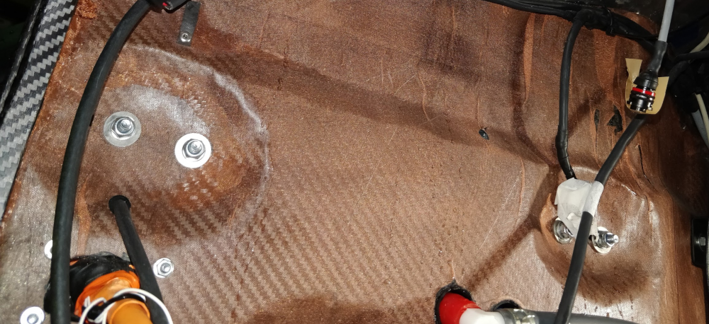
I'm trying to modelate what in formula student is called as a groove, this is a place where we take the core and unite the inner and outer layers of the monocoque (image below)
To build my model i followed the steps:
-Import a solid from the CAD, mesh the upper and bottom faces of the solid with a 2D mesh and then a 3D mesh to the solid;
-Changed the upper and lower face to another component to create the plyes, create them and the laminate.
-Create a property PSolid for the laminate and PComPP for the plyes;
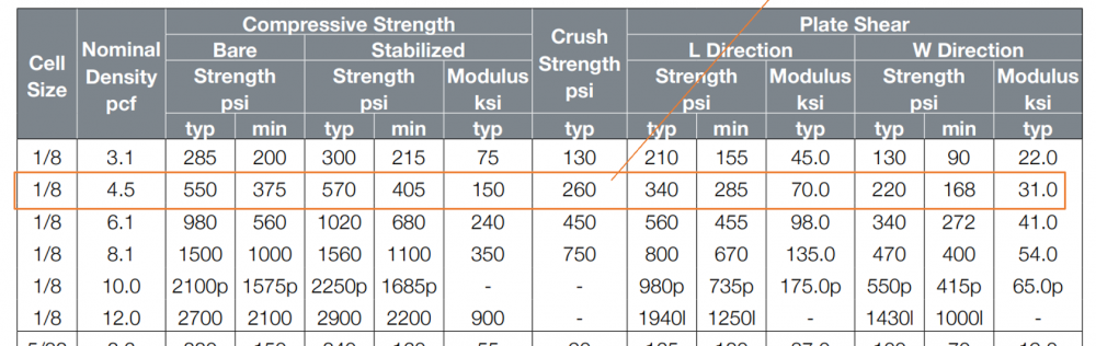
-Material for the core is a Mat1 and for the plies a Mat8
-The constraints and forces are in the image below. The force is applied in a rigid at a certain distance of the laminate
The problem is when i run i have a displacement of 1e+10 and i don't understand why
<?xml version="1.0" encoding="UTF-8"?>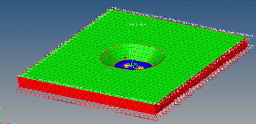
<?xml version="1.0" encoding="UTF-8"?>