🎉Community Raffle - Win $25

An exclusive raffle opportunity for active members like you! Complete your profile, answer questions and get your first accepted badge to enter the raffle.
Join and Win

Laminate Optimization Doubts

User: "Pedro Neves"
Altair Community Member
Updated by Pedro Neves

Hi guys,


I have some doubts about the laminate optimization.

1) When in the property of the laminate (PCOMPP) I choose the z0 option. If I choose top, the surface that I have for the laminate is really the top ply and Optistruct does the computations 'knowing' that it is the outter ply, or the z0 option is only for visual purposes to the user see what the laminate will look like in real life?

2) I also want to know if the forces aplied on the laminate will only act on the surface that is represented in Optistruct (outter surface if I choose z0 option top) or if Optistruct computes the distribution of loads based on the thickness of the composite, and applies the loads in all the plies.


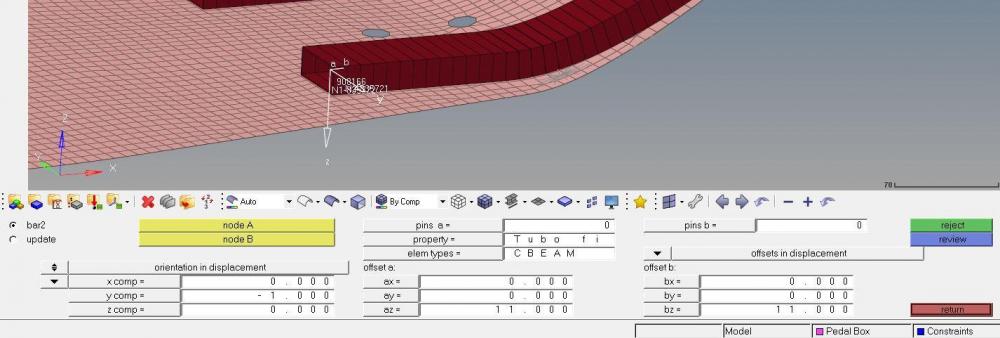
I have one last doubt about 1d elements and the offset that is set when i creat a CBEAM element. This offset is just for visual purpose, or it realy works like a way of keeping the connection between the 1D elements and the laminate in the centerline, but not necesseraly having the surface in the middle of the 1D element section?


Thanks for the atention, and if you don't understand my questions, tell me please! 

Find more posts tagged with

Sort by:
1 - 5 of 51
    User: "Pedro Neves"
    Altair Community Member
    OP
    Updated by Pedro Neves

    Can anyone answer to my post, please?

    User: "Rahul Rajan_21763"
    New Altair Community Member
    Updated by Rahul Rajan_21763

    It would be great if you can share hm file and the input image of laminate you are expecting.

    User: "Pedro Neves"
    Altair Community Member
    OP
    Updated by Pedro Neves

    I'm from a team of Formula Student, I'll share the model of the last years car for the purpose of trying to explain my questions because I'm not sure if I can share the model of the currents year car.

    -In the Image1, I have there elements CBEAM in the surface, to have a conection with the elements on it. But they have an offset from the surface, to simulate how it is in reality. This offset is just visual, or the program 'understands' that we want the CBEAM elements  with that offset and the calculations are done with that in mind?

    -In the Image2, being the blue surface 1 laminate with z0 top, and the surfaces applied on it (or using rigids that translate the force to the surface), the loads are only aplied on the outter surface or is it distributed by all the plies of the laminate?


    <?xml version="1.0" encoding="UTF-8"?>Image1.jpg

    <?xml version="1.0" encoding="UTF-8"?>Image2.jpg

    Unable to find an attachment - read this blog

    User: "Rahul Rajan_21763"
    New Altair Community Member
    Updated by Rahul Rajan_21763

    Ans 1. Beam offset is explicitly defined by the user consideration the actual situation of model.While reviewing beam you can see the beam offset details.

    Ans 2. Force acting on rigid will transfer to all the plies of the laminate.

    <?xml version="1.0" encoding="UTF-8"?>BEAM Offset.JPG

    User: "Pedro Neves"
    Altair Community Member
    OP
    Updated by Pedro Neves

    Thank you very much @Rahul R, now I'm 100% sure that my model is similar to reality!