Static Analysis with Contact
Ddear all
I want to analyze the maximum stress of the bolted joint to check the strength of the structure.
I use the RBE2 element to simulate a bolted connection.
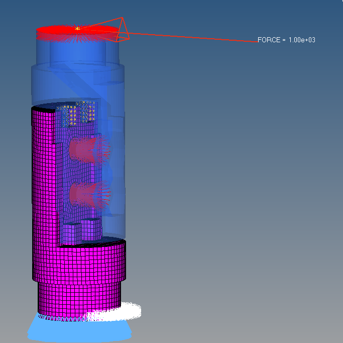
I bound the 6 degrees of freedom at the bottom, built the RBE2 element at the top, and loaded the force of 100N. as the picture shows:
I created 3 contacts to simulate the state of the actual force,
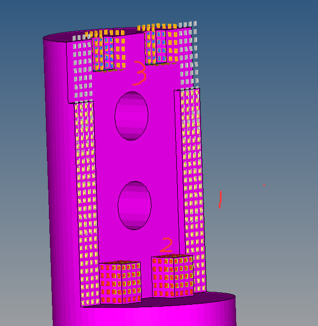
We intuitively analyze that due to the direction of the force, the contact 3 should have a large compressive stress, and the contact 2 should have no too much stress, but as a result, the contact 3 stress is small, and the contact 2 stress is large, which is why ?
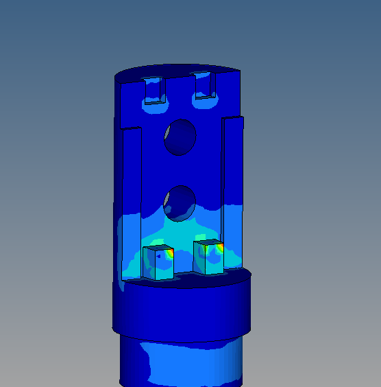
So I want to know how I should set it up? Is it wrong with my parameter settings for contact?
Thank you
Answers
-
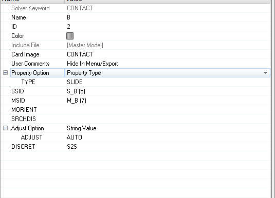
Can you just change the contact type from SLIDE to FREEZE and run again.
0 -
Altair Forum User said:
Can you just change the contact type from SLIDE to FREEZE and run again.
thank you,
The freeze is like a rigid body ?
BUt the Stress becomes bigger.The zz stress is 116MPa,,There should be no stress here..
0 -
Hi,
Sliding contact might not work using linear static analysis. In linear static analysis, the contact status does not change, does not slide and the contact stiffness is constant.
Freeze Contact enforces zero relative motion on the contact surface, the contact gap opening remains fixed at the original value and the sliding distance is forced to be zero. Additionally, rotations at the slave node are matched to the rotations of the master patch. The FREEZE condition applies to all respective contact elements, regardless of whether they are open or closed. Freeze Contact can be activated using TYPE=FREEZE on the CONTACT, MU1=FREEZE on the PCONT entry or by using the Penalty-based Tied Contact. Penalty-based tied contact is activated by using the TIE entry for the contact interface (with CONTPRM,TIE,PENALTY, the default).
I have set up a nonlinear quasistatic analysis (NLSTAT) and the model is attached.
<?xml version="1.0" encoding="UTF-8"?>
The contact forces are highest at the top and almost zero at the bottom, as expected.
<?xml version="1.0" encoding="UTF-8"?>
Essentially, it is a cantilever beam loaded in bending with maximum moment at the root (near fixed BC) and stress concentrations near abrupt changes of cross section.
0 -
If you're interested in the actual bolt forces and stresses, be sure to compare your current model with a full solid bolt model. There might be a significant difference.
0 -
Altair Forum User said:
Hi,
Sliding contact might not work using linear static analysis. In linear static analysis, the contact status does not change, does not slide and the contact stiffness is constant.
Freeze Contact enforces zero relative motion on the contact surface, the contact gap opening remains fixed at the original value and the sliding distance is forced to be zero. Additionally, rotations at the slave node are matched to the rotations of the master patch. The FREEZE condition applies to all respective contact elements, regardless of whether they are open or closed. Freeze Contact can be activated using TYPE=FREEZE on the CONTACT, MU1=FREEZE on the PCONT entry or by using the Penalty-based Tied Contact. Penalty-based tied contact is activated by using the TIE entry for the contact interface (with CONTPRM,TIE,PENALTY, the default).
I have set up a nonlinear quasistatic analysis (NLSTAT) and the model is attached.
<?xml version="1.0" encoding="UTF-8"?>
The contact forces are highest at the top and almost zero at the bottom, as expected.
<?xml version="1.0" encoding="UTF-8"?>
However, the stresses are greater at the bottom than the top due to the modeling assumptions (fixed boundary conditions, bolts simplified as rigid elements, load transfer through RBE2).
Thank you very much.
Maybe my version is low and I can't open the hm file. I use Optistruct to analyze the fem file error display:Is there something wrong?
What parameters do I need to reset?0 -
Altair Forum User said:
If you're interested in the actual bolt forces and stresses, be sure to compare your current model with a full solid bolt model. There might be a significant difference.
thank you very much。
If I build a solid model of a bolt, how do I set the relationship between the bolt and the joint? Using a common node or contact, how to simulate better?
I would like to see the stress of the joint instead of the stress of the bolt.
0 -
The model is able to run on my end (HW 2017.2). Try with the attached solver deck.
These modifications were made:
- PARAM>EXPERTNL>YES
- analysis>control cards>global output request>CONTF
- load collector with NLPARM card image
- non-linear quasi-static (NLSTAT) loadstep
0