Hello there,
I am working on setting up an Optistruct model for a FSAE carbon fiber monocoque.
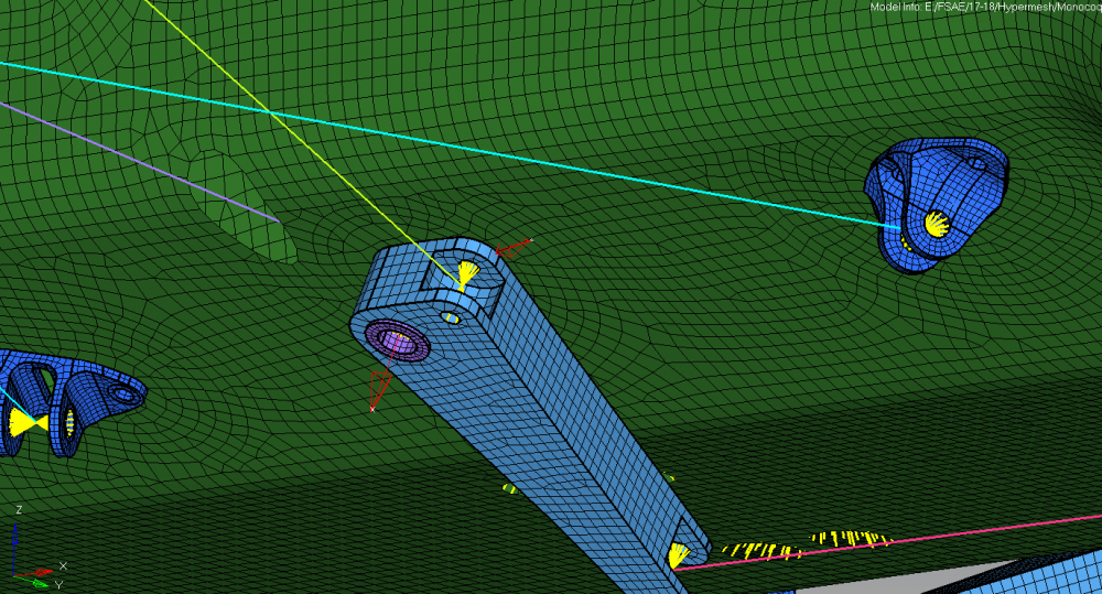
The bearings of the suspension arms are modeled as RBE2s with the corresponding DOFs.
In order to get the suspension to articulate somewhat realistically, I have added local coordinate systems that align with axes of the suspension components.
This way, the dependent nodes of the RBE2s can be assigned to the local coordinate system in order to set accurate DOFs for each rigid.
I attached a picture just for visual clarification of what I mean.
When modeling the first coordinate system and completing the steps listed above, the model solved.
When I create a second coordinate system in the same manner, I get this error below:
*** ERROR # 2113 ***
Invalid coordinate system CORD3R, id = 2
Coordinates of the 3 defining points are:
point 1 - -2.285920e+001 5.969279e+001 5.722970e+001
point 2 - -2.285970e+001 5.664590e+001 6.421403e+001
point 3 - -2.286030e+001 5.359900e+001 7.119836e+001
Any input is appreciated.
Thank you for your time.
Chris McCloskey
Michigan State Formula Racing
mcclos36@msu.edu
<?xml version="1.0" encoding="UTF-8"?>