How to correct the failed surface mesh part of a STL file

Altair Forum User
Altair Forum User
Altair Employee
edited October 2020 in Community Q&A

Dear all: 


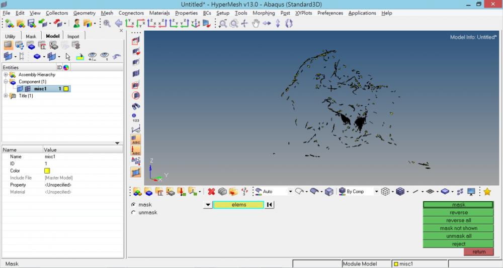
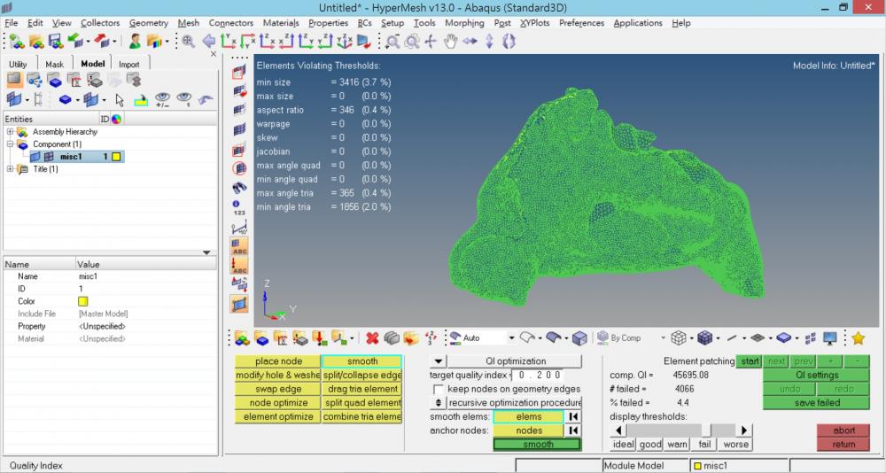
I am a doctor and just learned some basics of hypermesh from my friend. I am planning to use Abaqus to analyze the airflow in the nasal cavity, however, I have some problems in the surface meshing process. I already tried to smooth the original contour of the STL file, but still have some failed surface meshing part (about 4.4%). Is there anyway I can correct or adjust the nodes to make the failure rate to  0 % ? It would be really tiring to use the 'place nodes' function for thousands of times. Then I can go to the 3D mesh process inside and do numerical analysis.


Is there a video on youtube or some tutorials online? 


Thank you very much if there is any tip that can help me.


<?xml version="1.0" encoding="UTF-8"?>1.jpg
<?xml version="1.0" encoding="UTF-8"?>2.jpg

Tagged:

Answers

  • Rahul Rajan_21763
    Rahul Rajan_21763 New Altair Community Member
    edited April 2017

    Hi,

    If objective is to generate tetrahedral mesh on cavity.Then i would suggest to give a try with shrink wrap with all tetra option.I know your current process is too time consuming but you can give a try with this approach.Also please refer similar topic on below support forum post.


    <?xml version="1.0" encoding="UTF-8"?>Shrink wrap tetra.JPG

  • Altair Forum User
    Altair Forum User
    Altair Employee
    edited April 2017

    Thank you very much for your prompt reply. I have tried this method and the result seems good. 

    But I would like to know that is the mesh created with shrink wrap method is also a surface mesh ? or as your have mentioned above, it is already a 3D mesh with tetrahedron~

    Also, after using the shrink wrap method, it created some extra meshes (the red ones), is it possible to manually remove some of them (like those I am pointing with a white arrow)


    Thanks again !!


    <?xml version="1.0" encoding="UTF-8"?>3.jpg

  • Rahul Rajan_21763
    Rahul Rajan_21763 New Altair Community Member
    edited April 2017

    Yes it creates solid tetrahedral elements.Also make sure that imported geometry has correct dimension.I see you have used .6 mm element.By decreasing element size it would capture geometry properly.


  • Altair Forum User
    Altair Forum User
    Altair Employee
    edited April 2017

    Thank you Rahul for your reply, I have tried 0.4mm but it seems the created red parts still exist. I will try smaller elements later.  Thanks again !!