Highlights of the 2026 Release
The Feko 2026 release features extensions to many different solvers - enhancing Feko's capabilities in propagation modelling, network planning as well as general and specialist EM analysis application areas. There are various performance improvements, interoperability, and API extensions, enabling more flexible workflows and automation.
Feko
Performance
- Simulation times for large problems using MoM/MLFMM have been reduced dramatically. The impact is particularly large for models including ground planes and/or dielectric structures.
- The RL-GO solver used with point source and impressed antenna excitations has been enhanced, delivering greater computational accuracy and achieving performance gains of up to an order of magnitude in some cases.
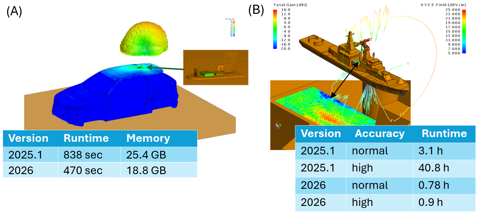
Performance comparison between Feko 2025.1 and Feko 2026 for antenna placement studies. (A) a 2.3325 GHz SDARS antenna mounted on a vehicle solved using MoM/MLFMM (196855 elements; 24 processors; PEC ground). (B) A 10 GHz slotted waveguide antenna mounted on a ship solved using RL-GO with a spherical mode source representation (5742 elements; 40 processors; 13.8 GB required for all cases).
Reciprocal Excitation Configuration
A new configuration type, the Reciprocal Excitation configuration, has been introduced.
Simulations using this configuration allow the computation of load responses (voltages and currents induced at loads) under plane wave excitation to be derived as a post-processing step, using the Reciprocal Configuration application macro in POSTFEKO.
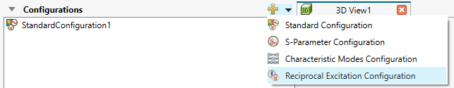
The new reciprocal excitation configuration in CADFEKO.
This workflow offers a computationally efficient approach to many EMC immunity and receiving antenna analysis problems, where only one simulation to compute far-fields is needed per source and/or load point (all loads including cable harness loads and schematic link connections are supported). With this information, the voltages and currents induced at these points can be extracted and analysed for any incident plane-wave direction.
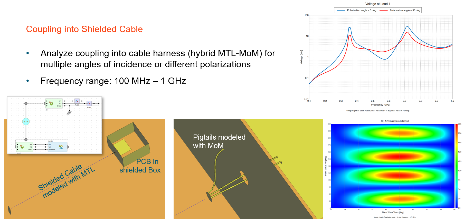
An example of coupling into a shielded cable using the reciprocity feature.
When analysing a direction-finding antenna array to determine port voltages as a function of direction of plane wave incidence, for example, the number of required simulations is reduced to the number of antennas × number of frequencies and is independent of the number of incident angles of interest. Incident plane wave properties - such as amplitude, polarisation, polarisation angle, and ellipticity - can be specified during post-processing.
Thick Coatings Using Multi-Layered Dielectrics
Thick coatings defined using multi-layered dielectrics are now supported on PEC faces on the boundary of closed regions (previously, only single layer dielectrics could be used in this way).
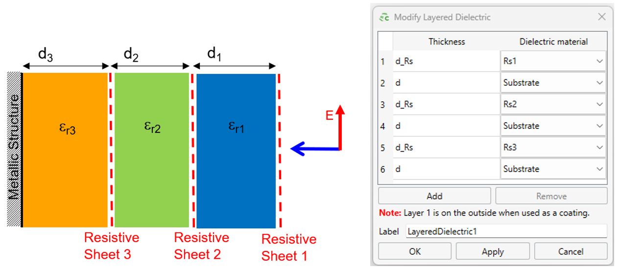
An illustration showing a thick coating consisting of multi-layered dielectrics applied to the surface oad a closed metalic (PEC) structure.
Adaptive Frequency Sampling Approach Integrated into Feko Solver
The adaptive frequency sampling approach has been integrated into the Solver. This approach requires fewer license checks, creates the .fek file only once (PREFEKO) and performs model setup and geometry checking phases only once irrespective of the number of frequencies solved. Integration also avoids the need to store, read and manipulate .bof files on disk - which caused performance degradation as the number of frequencies increased. For simulations where any of the factors mentioned contributed significantly to the total simulation time, the impact can be very dramatic when compared to ADAPTFEKO used for adaptive frequency sampling in previous releases. Additional benefits (such as the ability to use adaptive frequency sampling with AMRFEKO) are also clear.
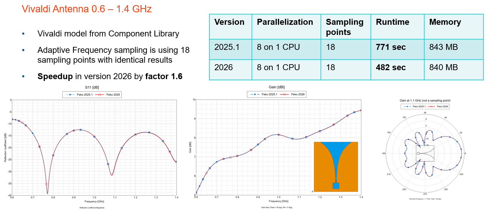
An example showing speedup by a factor 1.6 for a Vivaldi antenna in version 2026, when compared to version 2025.1.
Cable Modelling Extensions
Pin linking improvements
The Create Cable Instance dialog now supports simplified pin-to-pin connections:
- Sequential connection based on pin index order
- Label-based connection use signal labels to match pins (e.g., Shield or Core)
Circuit management
Added options to remove or duplicate circuits connected to selected cable connectors.
Duplicated circuits can be linked to another connector (even in a different harness) with
an optional name prefix.
Cable path creation
Added support to create a cable path from continuous wires or edges, automatically
combining them into a single path.
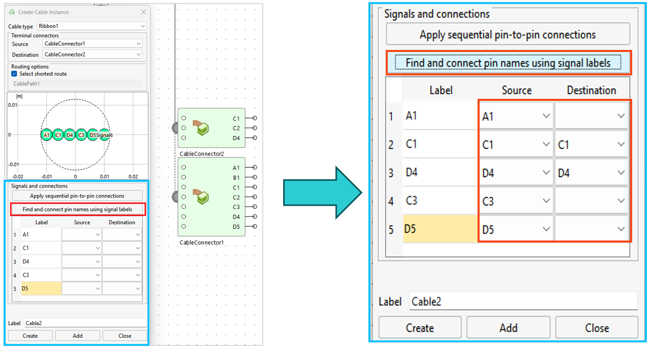
An example showing connections that were auto matched based on signal labels.
Data Import
When importing PCB data from ECAD formats such as ODB++, media properties and definitions are now recognized and imported where possible. If exact material properties are unavailable, materials with logical names are automatically created, simplifying the setup of simulation projects after ECAD import. Additional improvements, including enhanced arc and via representations have also been made in the ECAD import process.
API Extensions
The following POSTFEKO API extensions were made:
- Cable probe voltage data
- All voltage data computed using a cable probe can now be plotted on 2D plots and accessed via the API for automation. Previously, some voltages were unavailable for plotting.
- Multi-line tooltip notes
- Support added for multi-line text tooltips on stored data, which can also be set through the Lua API.
Remote Execution
Remote job execution now supports configuring of a Microsoft Windows host to launch jobs on Linux servers using a PowerShell envoke mechanism.
WinProp
Performance
Accelerated the SRT independently of the number of polygons, but can also be combined with a precomputation for further acceleration.
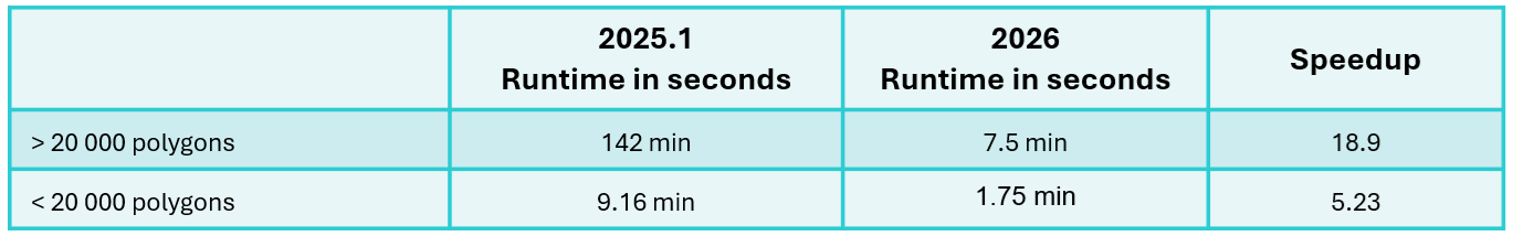
Examples showing the acceleration.
Radar Extensions
Pulse Radar
Support was added for Pulse Radar which is a radar system that transmits short, repetitive RF pulses to detect and track targets. Detection is achieved by measuring the echo time delay (determines range) and Doppler shift (determines radial velocity). The following waveforms are supported:
- Rectangular Pulse: simple but limited range resolution
- Frequency-Modulated Pulse: improves range resolution
- Phase-Modulated Pulse (Barker codes): offers good auto correlation properties
The Pulse Radar has matched filtering where the receiver correlates incoming signal with a reference (replica of transmitted pulse). It enhances the signal-to-noise ratio (SNR), improving detection sensitivity and accuracy.
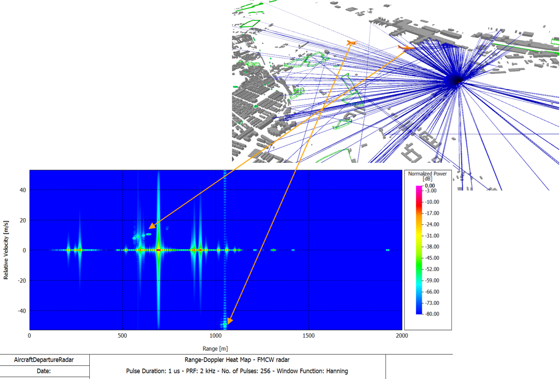
An example of air traffic radar that provides range and radial velocity of aircrafts.
FMCW radar post-processing
The FMCW radar post-processing was extended to 4D radar, enabling it to provide range, velocity, azimuth, and elevation information. This was achieved by adding the following extensions:
Constant False Alarm Rate (CFAR) parameters used for target detection
- Cell-averaging CFAR
- This algorithm can be used in most situations and estimates noise by averaging
power from reference cells.
- Greatest-of cell-averaging CFAR
- This algorithm is typically used when it is important to avoid false alarms at the
edge of clutter. It uses the higher average from leading or lagging reference cells to set a threshold.
- Smallest-of cell-averaging CFAR
- This algorithm is typically used when targets are closely located. It uses the smaller average from leading or lagging reference cells for the threshold.
- Order statistic CFAR
- This algorithm is a compromise between greatest-of and smallest-of cell averaging. It sets threshold based on a selected rank-ordered sample among reference cells.
Option to display the Range Elevation (AoA) heat map for vertical angle estimation
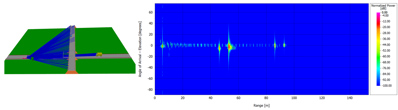
An example of a Range Elevation (AoA) heat map for vertical angle estimation.
Option to display the radar output as a point cloud
Each radar detection (range, Doppler, azimuth, elevation) is mapped into a 3D point in the space, which provides LiDAR-like visualization. Detection results in the point cloud depend on the defined CFAR settings.
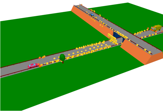
An example of radar output as a point cloud.
Consideration of Reflective Films via Bistatic RCS
Bistatic RCS as given in the .ffe file format to replace individual objects (for example, RIS) is now fully supported in ProMan. Rays having reflections before or after the interaction at the bistatic RCS are supported, also rays via multiple bistatic RCS. The bistatic RCS can be plotted depending on the incidence direction for which the individual RCS has been computed.
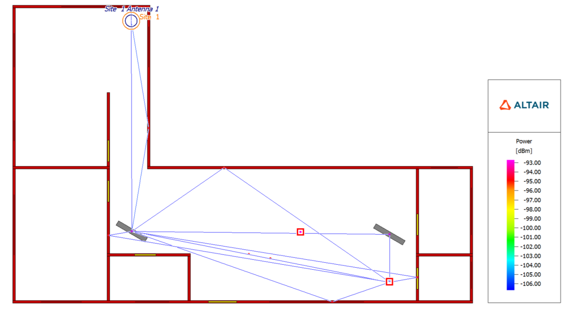
Bistatic RCS as given in the .ffe file format to replace individual objects (for example, RIS) is now fully supported in ProMan.
The bistatic RCS can now be plotted in ProMan, depending on the incidence direction.
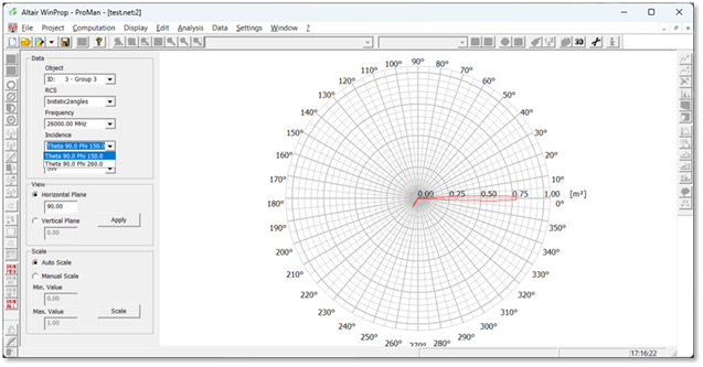
The bistatic RCS can now be plotted in ProMan.
Combining Tunnels with Pixel Topography in Indoor SRT / DPM
Support was added to allow entering and exiting tunnels when being combined with pixel topography in SRT/DPM.
Example of an environment with pixel topography featuring a tunnel entrance/exit, showing rays exiting the tunnel.
