This article provides a step-by-step guide for performing a structural analysis on polyhedral particles using force data exported from an EDEM simulation. The workflow involves mapping EDEM forces onto a finite element mesh in HyperMesh and running a static analysis in OptiStruct.
Note: This workflow is specifically designed for simulations containing polyhedral particles.
Prerequisites
Before you begin, ensure you have a completed EDEM simulation with polyhedral particles.
Step 1: Export Data from EDEM
The first step is to export the necessary files from your EDEM simulation. You will need the particle geometry, material definition, and corresponding force data at a specific time step.
- Open your completed simulation in the EDEM Analyst.
- Navigate to
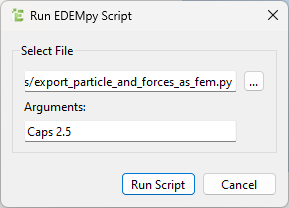
File > Run EDEMpy Script. - In the new window, select the script named
export_particle_and_forces_as_fem.py and, under arguments, write the particle name and the time to export the data.
This script will generate two critical files:
- A
.fem file containing the 2D surface mesh of the particle with the highest compressive force and its material properties. - A
.csv file containing the forces acting on that particle. - The values in the files are all in SI units.
These two files are the inputs for the structural analysis in HyperMesh and OptiStruct.
Step 2: Import the Particle Mesh and Material
Begin by importing the particle surface mesh and its material in HyperMesh.
- Navigate to
File > Import > Solver Deck.
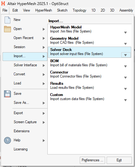
- Select the
.fem file that you exported from EDEM. - Click Import.
- This will load the 2D shell mesh representing the particle's geometry and will also create the corresponding material in the model.
Step 3: Map EDEM Forces onto the Mesh
Next, you will map the forces from the .csv file onto the nodes of the imported 2D surface mesh using a Field.
- In the Model browser, right-click anywhere, then
Create > Fields > Create.
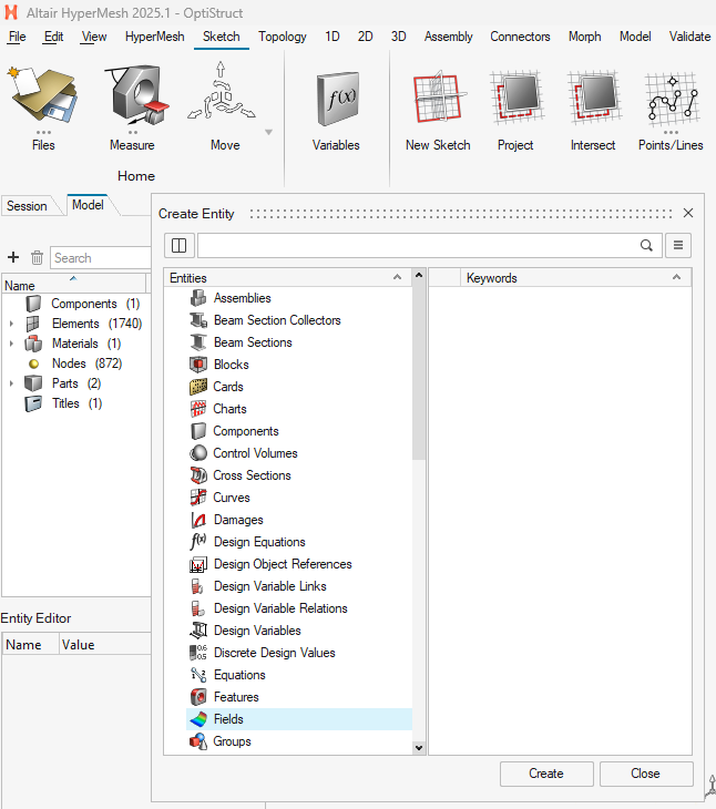
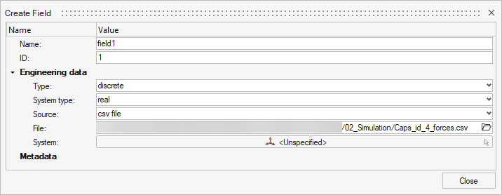
In the Field creation panel, configure the following:
- Field Type:
Discrete (since the CSV contains data at discrete points). - Source:
CSV File. - File: Select the
.csv file exported from EDEM then click Close.
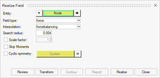
Double-click on Fields then right-click on field1 then click on Realize. In the new window:
- Entity: Click on the
▼ button and select Node. Then click on Node and select all nodes of your particle mesh. - Type: Select
Force. - Interpolation: Select
Force Balancing. - Search Radius: Enter a small value (e.g.,
0.004. This value will change depending on your mesh's size). - Click on
Realize to realize the field then click Close.
Step 4: Generate a 3D Solid Mesh
With the forces mapped to the surface nodes, you can now create a 3D solid (volume) mesh from the 2D surface mesh.
- Go to the
3D > Tet panel from the main menu bar. - In the
Tetra mesh sub-panel, select the component that make up your particle's surface mesh. - Review the meshing parameters, such as element size and quality settings. For most initial analyses, the default values are sufficient.
- Click Mesh to generate the 3D tetrahedral elements.
- After the 3D mesh is created, it is good practice to delete the original 2D surface mesh to keep the model clean.
- On the model browser, expand the
Elements entity. - Right-click on 2D then click Delete.
Step 5: Define and Assign Physical Properties
Now you will define a physical property for the solid mesh and assign a material to it.
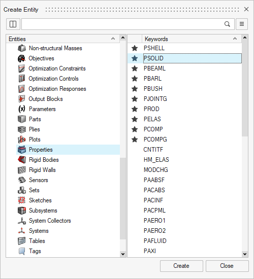
- Right-click in the Model Browser and select
Create > Properties. Select PSOLID then click Create - Name the property (e.g.,
property1).
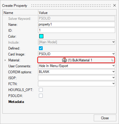
- Name the property (e.g.,
property1). - In the property editor, click on the Material selection box.
- Select the material that was imported with your
.fem file. It should already be listed. Click on Close.
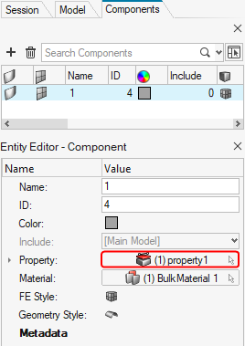
- In the Model Browser, double-click on the
Components entity and, in the new browser, select the component containing your 3D mesh. - In its details panel, assign the property you just created.
Step 6: Set Up Inertial Relief for Analysis
Since the particle is an unconstrained body (i.e., free-floating in space), a standard static analysis will fail due to rigid body motion. You must enable inertial relief to solve this.
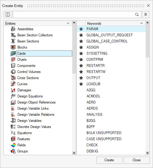
- In the Model Browser, right-click and select
Create > Cards. Select PARAM then click Create.
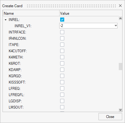
- In the card editor that appears, find the parameter
INREL and set its value to -2.
Step 7: Create the Load Step and Run the Analysis
Finally, define the analysis case by combining the loads and boundary conditions, and then launch the solver.
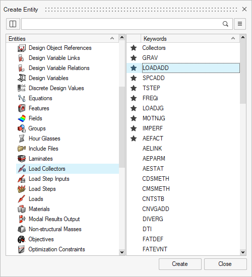
- In the Model Browser, right-click and select
Create > Load Collectors, select LOADADD then click Create.
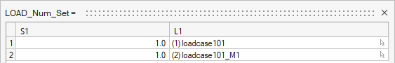
- Click on
Loadcol List then click on ... and select both load cases. - Click on button next to
Data: S1 and set the S1 value for both load cases to 1.
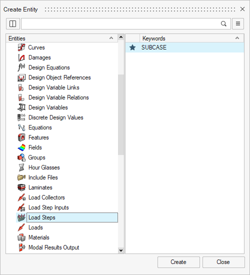
- In the Model Browser, right-click and select
Create > Load Steps then click Create.
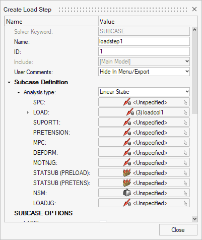
- In the load step's settings panel, define the analysis:
Analysis type: Linear Static.LOAD: Select the loadadd collector created in the previous step then click Close.
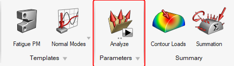
- From the top menu, select
Analyze then click on Run. On the new window, save your model using a different name.
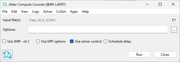
- Click
Run on the Compute Console to launch OptiStruct.
Conclusion
Once the analysis is complete, you can view the results (e.g., stresses, displacements) in Altair HyperView. This workflow allows you to determine the internal structural response of polyhedral particles based on the dynamic forces calculated in an EDEM simulation.
