In battery manufacturing, aluminum foil is widely used as the current collector for the cathode due to its excellent electrical conductivity, corrosion resistance, and low density. During the electrode fabrication process, large sheets of coated aluminum foil are precisely cut into the required shapes through a process known as notching. While notching is essential for preparing electrodes for cell assembly, it can introduce mechanical damage to the aluminum foil, which may adversely affect battery performance and yield.
Common forms of aluminum foil damage during notching include burr formation, microcracks, edge deformation, and localized delamination of the active material coating. Such defects can lead to increased internal resistance, non-uniform current distribution, or even particle detachment, which in turn may contribute to short circuits, capacity fade, or premature cell failure.
The occurrence of damage is influenced by multiple factors, including foil thickness, mechanical properties of the foil and coating, blade sharpness, cutting clearance, and process parameters such as speed and applied force. Understanding the mechanisms behind aluminum foil damage during electrode notching is therefore crucial for optimizing manufacturing processes, improving electrode integrity, and ensuring the reliability of high-performance batteries.
Background:
The purpose of electrode notching in battery manufacturing is mainly to prepare electrode sheets (coated metal foils) into the exact shapes and dimensions needed for cell assembly, while ensuring proper mechanical fit and electrical performance.
Objective:
This study aims to evaluate the effect of cutting speed on electrode notching performance, with emphasis on
- Cutting force
- Stress–strain characteristics of the aluminum foil
- Foil Damage
Prerequisites:
EDEM-OS two-way coupling requires below specified version or later versions
- EDEM – 2025.1
- OptiStruct– 2025.1
- SimLab – 2025.1
Simulation Methodology:
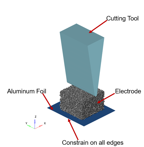
The following simulation methodology is adopted for notching
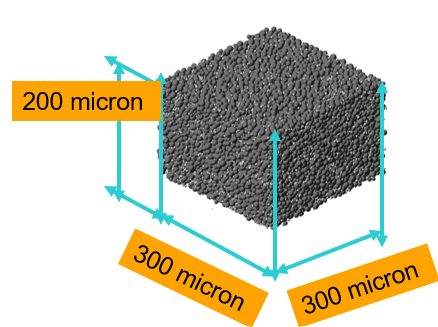
- Electrode is modelled with particulate materials using EDEM
- Cutting tool, Aluminum foil are modelled using Finite Element method i.e OptiStruct-Explicit
- Cutting tool moves with a velocity as 0.2 m/s
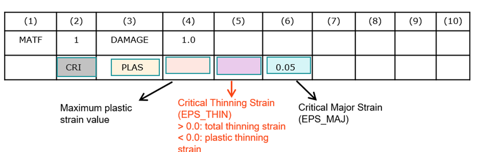
- Damage criteria are chosen based on plastic strain failure criteria shown in below picture
Key Points To be Noted:
- Electrode is modelled using non-calibrate material model
- Foil is assigned with Non-linear Aluminum material i.e Yield strength of 358.1 Mpa
- Cutting tool is assigned with linear steel
- Aluminum foil is modelled as shell element
EDEM Setup:
The following steps are used to create a particle bed
- Define the bulk material properties
- Define the Particle to Particle and Particle to geometry Interactions
- Define the particle shape, size and its distribution
- Define particle-to-Particle and Particle-to-Geometry using EEPA and Standard rolling friction physics model
- Add Bonding V2 Physics model in particle-to-particle interaction to establish bond between electrode and cathode material
- Define Periodic boundary Condition in X and Y axis
- Define Raleigh Time Step with time step as 2.787E-09 sec
- Run the Simulation
- Export the Simulation Deck at time step = 0 sec
- Open the Exported simulation deck
- Delete the factory
- Switch on the coupling server
SimLab Setup:
Simulation Results:
To simplify the learning process, the following files are provided with the blog:
- EDEM simulation files with a particle bed
- FE model setup for electrode cutting using SimLab
- A .fem file containing the electrode cutting tool and the modeled aluminum foil
Simulation Files:
EDEM Files:
FE Input File:
SimLab Setup File:
If you are looking for further information on EDEM or other Altair products we have plenty more on the Altair Community: