Implementation of CC-CV in PSIM
Battery charging systems are typically designed with the primary goal of maximizing battery health and lifespan. Among the most widely adopted strategies is the Constant Current–Constant Voltage (CC-CV) charging method. This article outlines the implementation of a CC-CV algorithm using a buck converter in PSIM, highlighting control strategies, mode transitions, and simulation results to validate the approach.
I. System Specifications
- Battery Model:
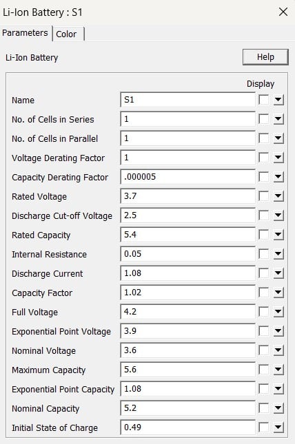
2. Buck Converter Parameters:
Input Voltage: 12V
Inductor (L): 50uH
Capacitor (C): 200uF
II. Control Architecture and Implementation
Dual-Loop Controller Design:
A two-loop control architecture is implemented using PSIM’s SmartCtrl tool:
- Outer Voltage Loop: Regulates the battery terminal voltage and generates a reference current (
I_ref) for the inner current loop. - Inner Current Loop: Tracks
I_ref by controlling the inductor current, generating the necessary PWM duty cycle via a PI controller.
This structure alone typically functions in CV mode. However, the PI parameters derived from this configuration are reused and extended for CC-CV operation.
CC-CV Charging Logic
The core algorithm operates in two distinct modes:
Constant Current (CC) Mode:
- Objective: Maintain a fixed charging current.
- Implementation: The inductor current is sensed and compared with a fixed reference current. A PI controller processes the error and adjusts the PWM duty cycle to regulate the current.
- Result: Battery voltage and SOC increase during this phase.
Constant Voltage (CV) Mode:
- Objective: Maintain a fixed battery terminal voltage.
- Implementation: The battery voltage is sensed and compared with a reference voltage. The resulting error is passed through a PI controller to generate the current reference, which is then regulated by the inner loop.
- Result: Charging current gradually reduces to zero as SOC approaches 100%.
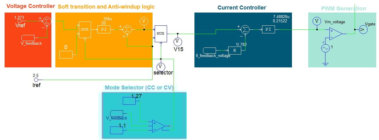
The following figure gives the idea to implement this logic.
Mode Selection and Transition Logic
The charging mode is dynamically selected based on battery terminal voltage:
- CC-to-CV Transition: Triggered when battery voltage reaches a defined threshold (e.g., 1.1 V).
- CV Regulation Band: Ensures voltage remains below the upper limit (e.g., 1.27 V) to avoid overcharging.
A hysteresis band is employed to prevent frequent toggling between modes near the threshold. The mode selector block handles this transition seamlessly.
Anti-Windup and Transition Smoothing
To avoid control saturation and ensure smooth operation during mode transitions, the following techniques are applied:
- Anti-Windup: Prevents integrator windup in the PI controllers when switching between CC and CV modes.
- Slew Rate Limiting: Ensures gradual change in reference signals, minimizing voltage or current spikes.
These measures guarantee stability and robustness during the entire charging cycle.
In the implemented CC-CV charging logic, the system begins in constant current (CC) mode, where the battery is charged at a fixed current (e.g., 2.5 A). During this phase, the MUX selects a constant zero input for the voltage PI controller, effectively keeping its output at zero. This ensures that the current loop receives a clean reference without interference. When the battery voltage reaches 1.1 V, the system transitions to constant voltage (CV) mode. At this point, the voltage PI controller becomes active, but to avoid a sudden drop in current reference (which could cause a spike due to mismatch), the PI output is added to the previous Iref (2.5 A). The PI output is saturated between 0 and -2.5, so the total Iref gradually decreases from 2.5 A to 0 A, allowing a smooth and spike-free transition from CC to CV mode.
III. Simulation Results
The following figure shows the results of battery charging as discussed above.
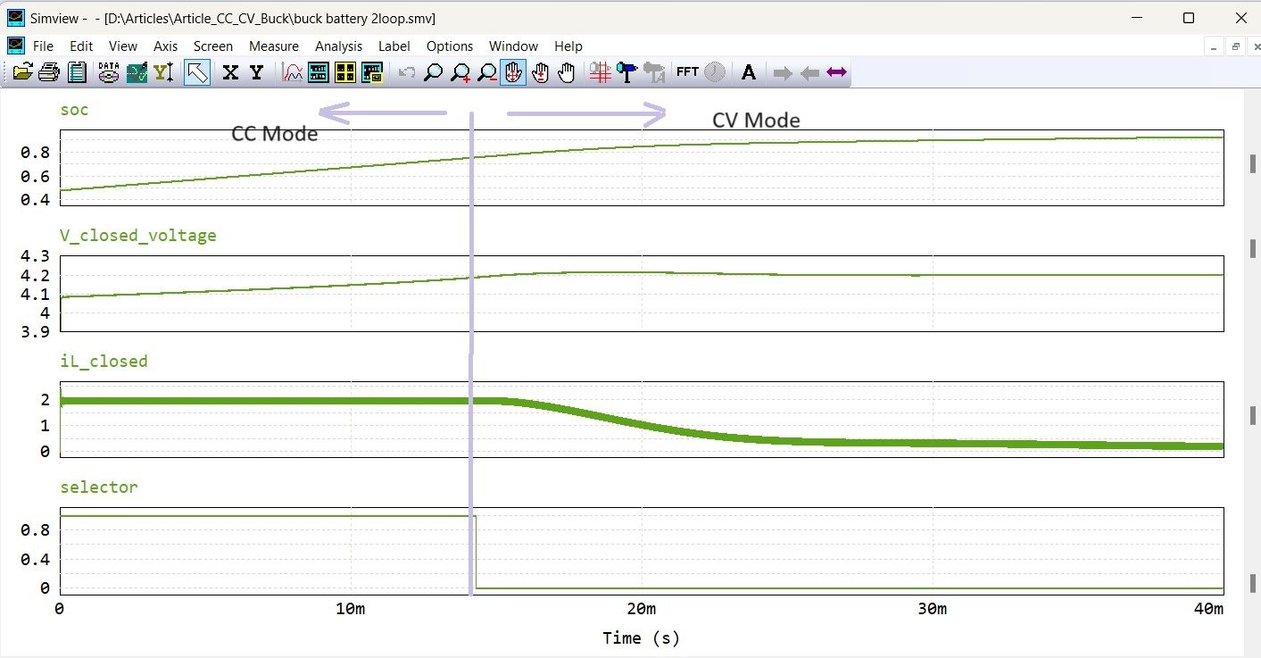
The simulation results validate the effectiveness of the proposed control strategy. The battery undergoes:
- A CC phase, where current is maintained while voltage ramps up.
- A CV phase, where voltage is regulated and current smoothly decays to zero.
A clear and stable transition between modes is observed, demonstrating the practical feasibility of the implemented algorithm.
Simulation Files:
Learn More:
- Application note for the control of a buck converter with peak current control, PCMC, and PSIM - Altair Community
- Peak Current Mode Control (PCMC) on Buck Converter - PSIM - Altair Community
- PSIM & SmartCtrl - Design a Controller in Minutes, Not Hours - Altair Community
