Foreword
I’m excited to share the innovative work of my colleagues, Nadine Kåmark and Christoph Mäurer, who have tackled the complex challenge of automotive radar integration under severe vibrations. Their research demonstrates how Altair’s HyperWorks suite can model and analyze the impact of dynamic conditions, such as hard maneuvers and road bumps, on radar performance in modern vehicles. By combining structural, multibody, and electromagnetic simulations, Nadine and Christopher provide a robust methodology to optimize radar placement, ensuring safety and reliability in advanced driver-assistance systems (ADAS). Their work, detailed below, showcases innovative solutions with real-world applications for automotive safety standards. Join me in exploring their insights, and feel free to share your thoughts with our community!
// Erik Magnemark, Altair - Mechanical System Simulation
Introduction
Automotive radars are becoming standard equipment on vehicles. Their purpose is to adjust the distance between vehicles and/or alert the driver when dangerous situations arise.
Since 2010, the safety functions became more and more important and included in the last automotive standards (ex: EURONCAP) for 5 stars’ level. Automotive OEM’s are now moving to include several safety systems covered by several sensors to reach the 5 stars’ level safety standards.
Several antenna architectures are used to cover the different safety functions in complex bumper/car chassis environment where the side effects become more and more significant on the radar performances. Hence, automotive radar integration process becomes a very important topic. Weak radar integration will generate gain loss, high side lobes levels and angular errors. Those degradations will impact the radar range, the main radar axis (BSE) and the radar detection quality (resolution, ambiguity, discrimination …).

In addition, vibrations during situations such as hard maneuvers or bumps on roads may significantly modify the position of the radar with respect to the rest of the structure, mainly the bumper, causing some responses changes which must be taken into account. The purpose of this demonstration is to show how vibration effects can be calculated with Altair’s HyperWorks solver suite.
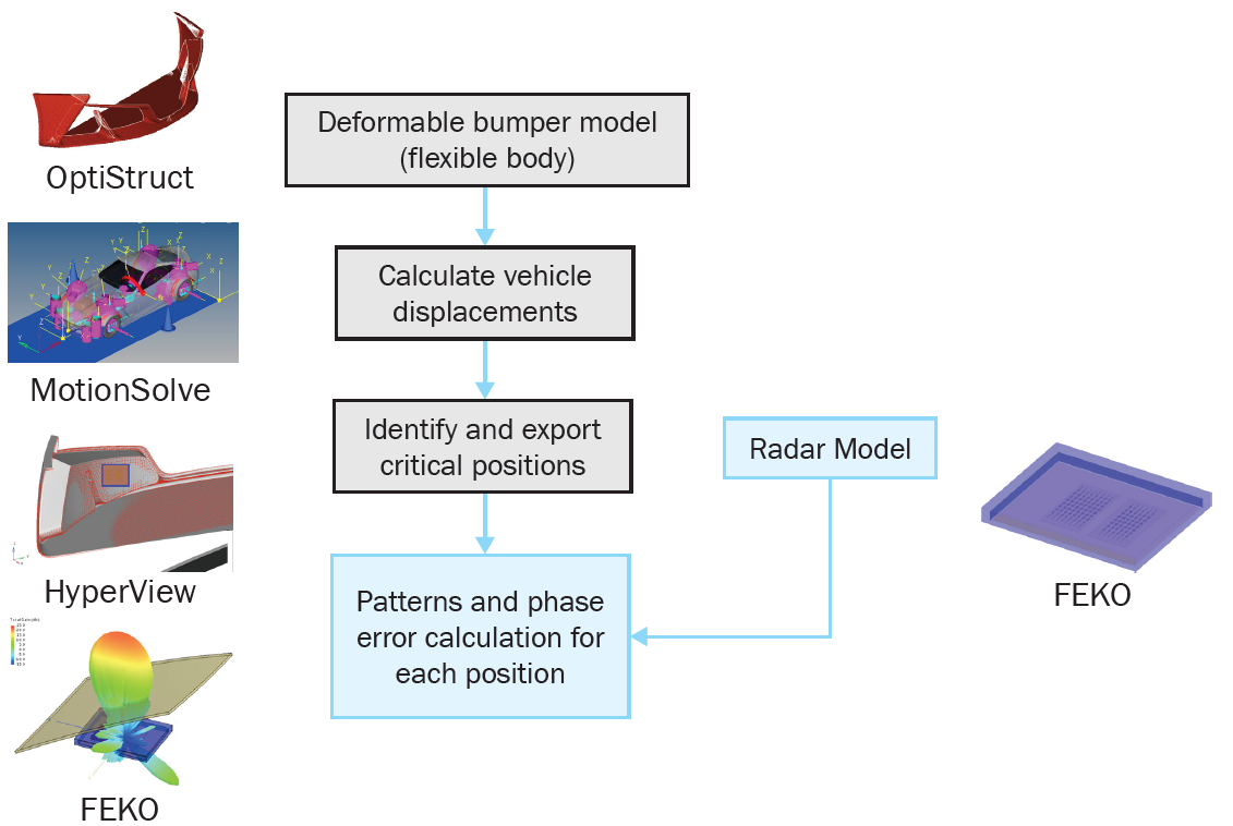
The car model is a multibody model where the bumper is modelled as a flexible body, using OptiStruct®. The global movement of the vehicle is calculated using MotionSolve®. Critical times are identified based on the maximum and minimum distance between the radar and the bumper and the deformed geometry at those times is exported to FEKO. A calculation of the phase error and the radar pattern is then performed and compared to the “nominal situation”.
Effect on the bumper
The bumper is shadowing the radar antennae, with consequences on the radar performances depending on thicknesses, dielectric properties of the material, shape and angle of incidence between the radar and the bumper
The bumper induces several types of errors, mainly:
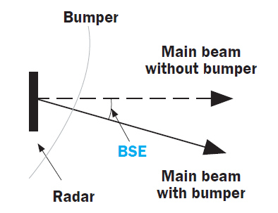
- BoreSight Error (BSE) : If the peak of the main lobe level is deviated from the reference data, the obstacles are detected out of the main
radar axis, thus creating an angle difference between the target’s actual position and the radar indicated position
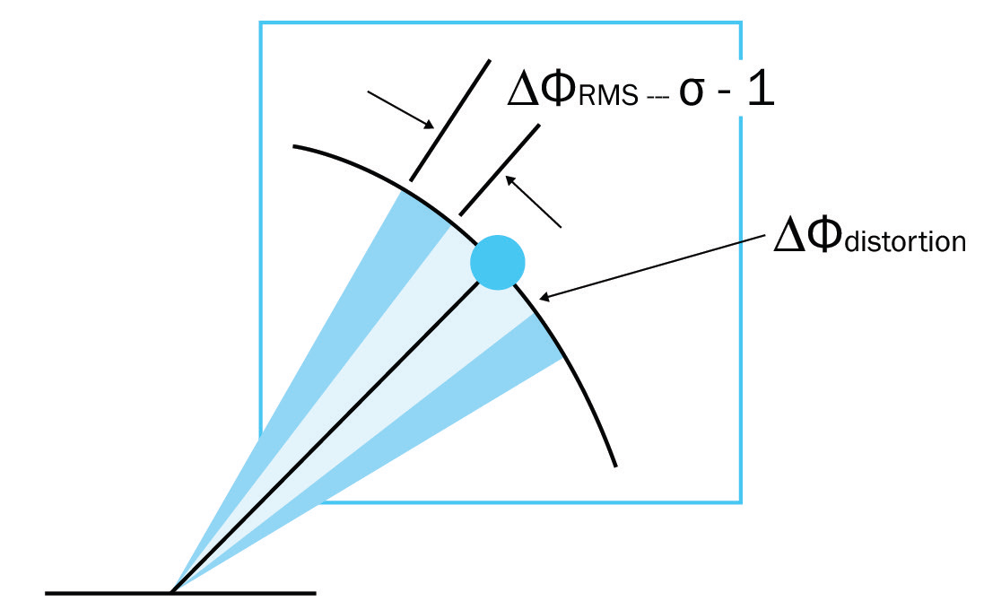
- The phase error is the result of bumper shape and wave front distortion and is responsible for erroneous object displacements.
Structural Model
In this project, the bumper is modeled as a deformable component. It is represented as a flexible body within the multibody car model to capture its deformations under severe road conditions, such as hard bumps and aggressive lane changes. A generic bumper, defined by a simplified geometry and material properties, is considered. Deformational modes in the frequency range of 10–120 Hz, selected based on modal energy contribution, were retained. The calculations were performed using OptiStruct, employing a finite element (FE) model reduced via the Craig-Bampton method for integration into the multibody simulation
The finite element (FE) model of the bumper was developed in SimLab, utilizing its automated high-quality meshing capabilities and intuitive multibody load case setup.
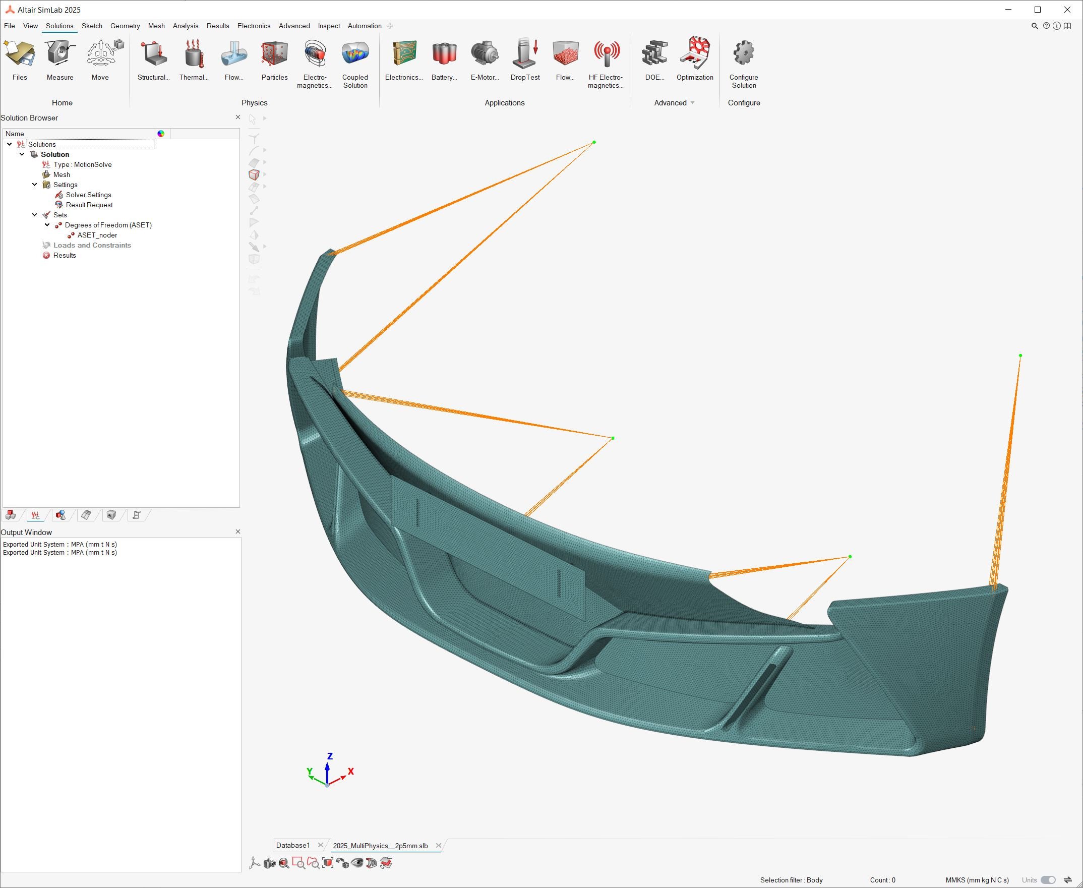
The resulting Bumper flexbody (.h3d file) contains graphical body representation as well as the orthogonal deformation modes from the CMS condensation that will later be available for use of the MultiBody solver MotionSolve.
Utilizing the MotionView Vehicle Tools allows for a fast topological full car model to be built and easily modified to any specifications and test data requirements.
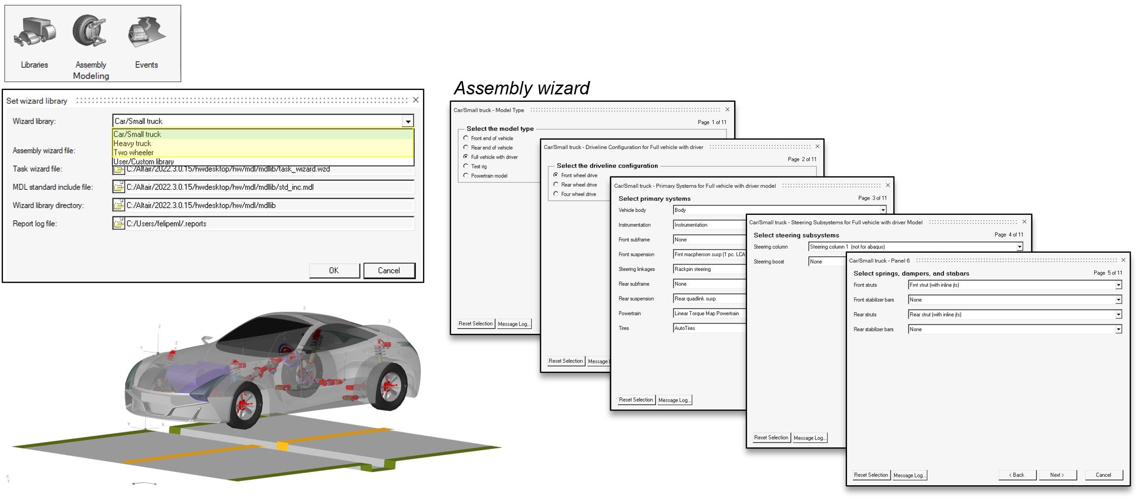
In this model, suspension, driveline, tires, driver, and event components were created. The flexible bumper is attached to the vehicle's corresponding connection point, and dynamic handling load cases were applied, setting up two load cases, showing the Bumper deformation during the events:
Double lane change
Pothole (1 sided)
Radar response
The radar response needs to be calculated only at the most critical times. They are determined by checking the relative translational and angular displacements and retaining only the maximum values within each loadcase.
The deformed geometry of the bumper is saved in HyperView® and imported to FEKO. New calculations are performed using the deformed geometries. The results for each Tx and Rx are then compared, as in graphs below:
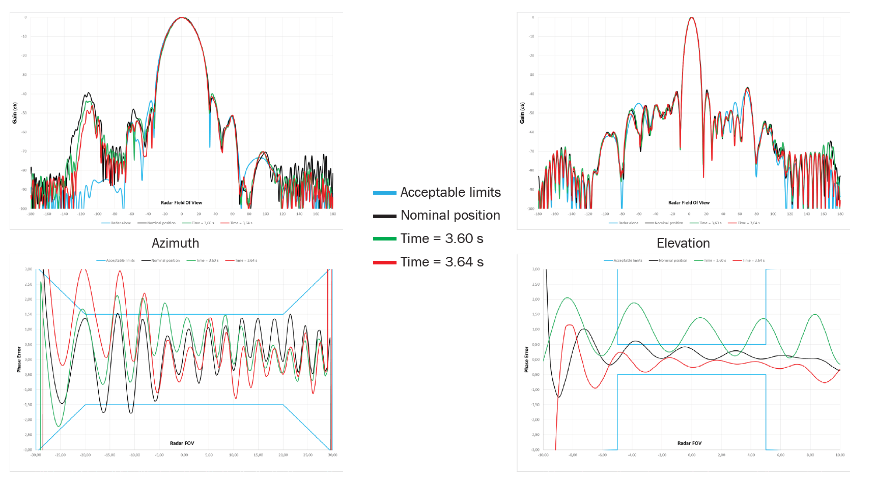
Results: Amplitude patterns and phase error at critical times from a previous event. In this case It can be seen that the phase error, either in azimuth or elevation are clearly out of the corridor. In this case, a new placement of the radar would be required.
Pothole loadcase results:
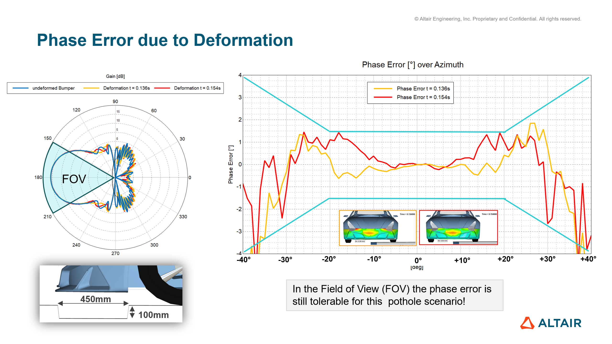
Results: Phase error due to de bumper deformations of Pothole event. The Field Of View is defined as +-20deg, and within this range we want to have a phase error less than +- 1.5. The light blue lines indicates the threshold and as you can see we are within the acceptable range of +-1.5 for this loadcase.
Conclusion
The placement of the radar must take into account the vibrations of the car that may occur during harsh maneuvers. The consequences of those events can be calculated using HyperWorks, opening the possibility of optimizing its placement to minimize the degradation of the response.
Hyperworks suite is highly suited to this type of applications as global vehicle movement, vibrations and high frequency Electromagnetic simulations can be calculated in the Hyperworks environment (using MotionSolve, OptiStruct and FEKO respectively) creating a global process. Moreover, HyperStudy can help the design engineers by providing a multi-disciplinary optimized solution taking into account both electro-magnetic and structural requirements, even though they may conflict.
More generally, this methodology demonstrated here can be generalized in any situation where possible deformations and vibrations of the
radar environment may affect its performances, such as drones and other vehicles
Altair ADAS White paper:
DOWNLOAD LINKS:
MotionSolve simulation models (Double Lane + Pothole): ADAS_MotionView.zip
SimLab FEM model of Bumper flexbody: ADAS_FEM.zip
