Dear Users,
With this article, I’d like to shed some light on how the PLL (Phase-Locked Loop) block functions and provide insights into the underlying modeling approach.
To illustrate this, let’s consider the following simple setup:
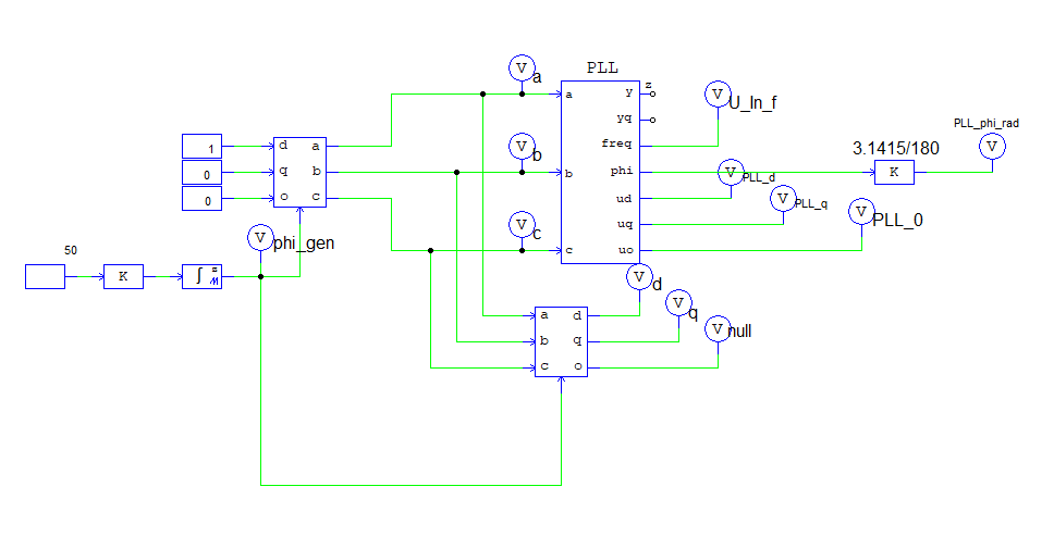
When the setup is run, we get the following results:
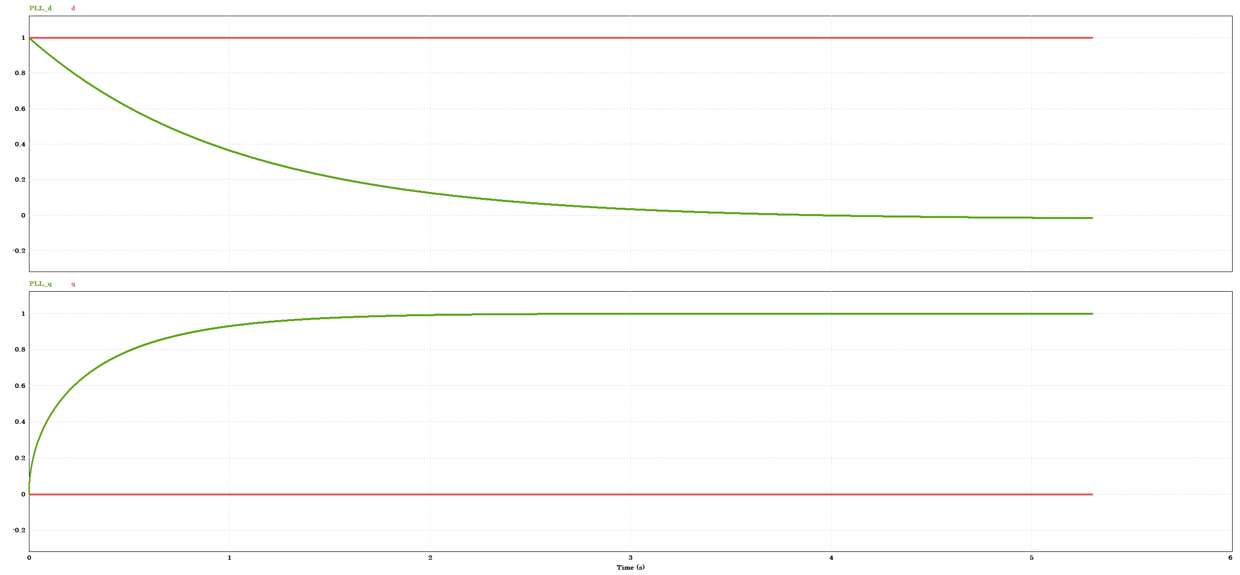
In this example, the reference d axis value is set as 1 and the q-axis value is set as 0 in the reference dq0 to abc block. However, the PLL block in PSIM outputs that the d value converges to 0 and the q value to 1. So it seems as if PSIM inverted the inputs.
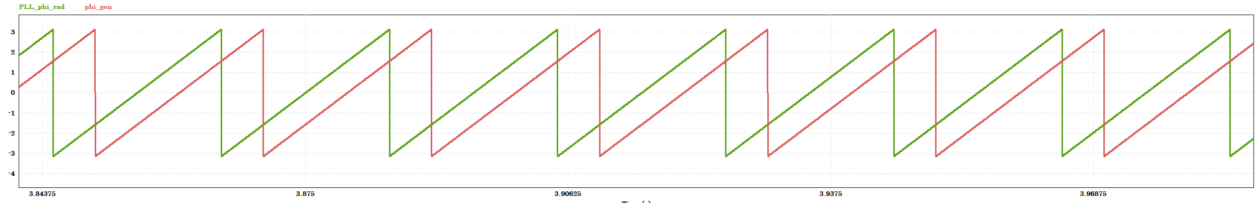
There is also a phase shift between reference and the reading of the PLL block.
In summary, the issues observed in this simulation are:
1. The d value of the PLL block output always converges to 0 no matter what.
2. There is a 90 deg. phase difference between the theta of the PLL output and the original theta that is used to perform the abc-dqo conversion
TEXT-BASED ANSWER
While you probably expected that PLL_d was going to be the same as d and PLL_q the same as q, that's actually not the case due to two reasons.
1. The first reason is that when dqo is converted to abc, there is an additional phase angle that needs to be considered due to the dq quantities [more on this reason in the math explanation later if you want to have a look].
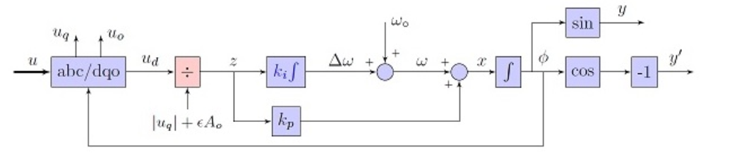
2. The second reason is the setup of the PLL block diagram. Internally, the PLL block uses an abc/dqo block with transformation_flag = 1, and it has a PI control loop that tries to achieve vd to be 0, as shown from the block diagram below. This is why the d-axis value of the PLL output always converges to 0 eventually.
In order to achieve vd = 0 of the internal abc/dqo block, with transformation_flag = 1, using the expression vd = Vpk*cos(theta_s - theta), it means that the phase difference (theta_s - theta) must be +/- 90 deg. In the test circuit (the attached "dev_team_abc-dqo-PLL.psimsch"), it means that theta_PLL_cos and theta_s should be 90 deg. apart This is where the difference of 90 deg. comes from.
You may question, "why the resulting theta is set to be 90 deg apart from the Vabc angle?". Well, this is how the 3-phase PLL block is set up to work with cos based signals (there is a workaround presented later). In the real life, you typically do not generate abc signals in this way. As you can see from the example "examples\PLL blocks\3-ph inverter - PLL.psimsch", once you convert the abc quantities to dqo, you work in the dqo frame and eventually convert back to abc using the dqo/abc block.
As long as you do this and are consistent, the phase difference of 90 deg. does not come into play. Please note, since all 3-phase PLL blocks use transformation_flag = 1 internally, in the circuits that use these blocks, one must use transformation_flag = 1 also for all abc/dqo or dqo/abc blocks. Otherwise, the circuit will not work.
If you want to get rid of the 90deg shift you can generate the abc voltages with sine based signals as shown below [attached as "dq_without_shift"] and use transformation_flag = 1 for dq/abc - abv/dq blocks:
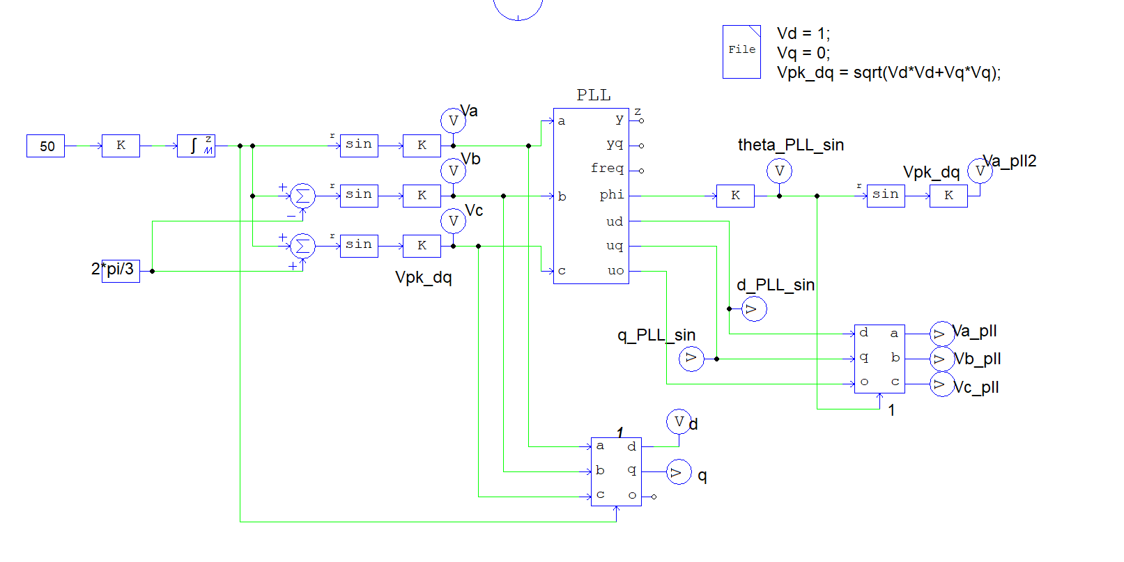
If Vabc are sine based, vd = Vpk*sin(theta_s - theta). For vd = 0, theta_PLL will be the same as theta_s. In the simulation, Va = Va_pll = Va_pll2. And the d / d_PLL_sin signals as well as q / q_PLL_sin signals will match.
That was my effort to summarize the math the best way I could. I hope it helps - if you can use some extra math regarding this topic, please continue reading.
MATH-BASED ANSWER
Will be using the attached circuit "abc-dqo-PLL.psimsch" to answer the questions (vd always converges to 0 and 90deg shift). The circuit uses the s-domain version of the 3-phase PLL block. But it should be the same with the z-domain block.
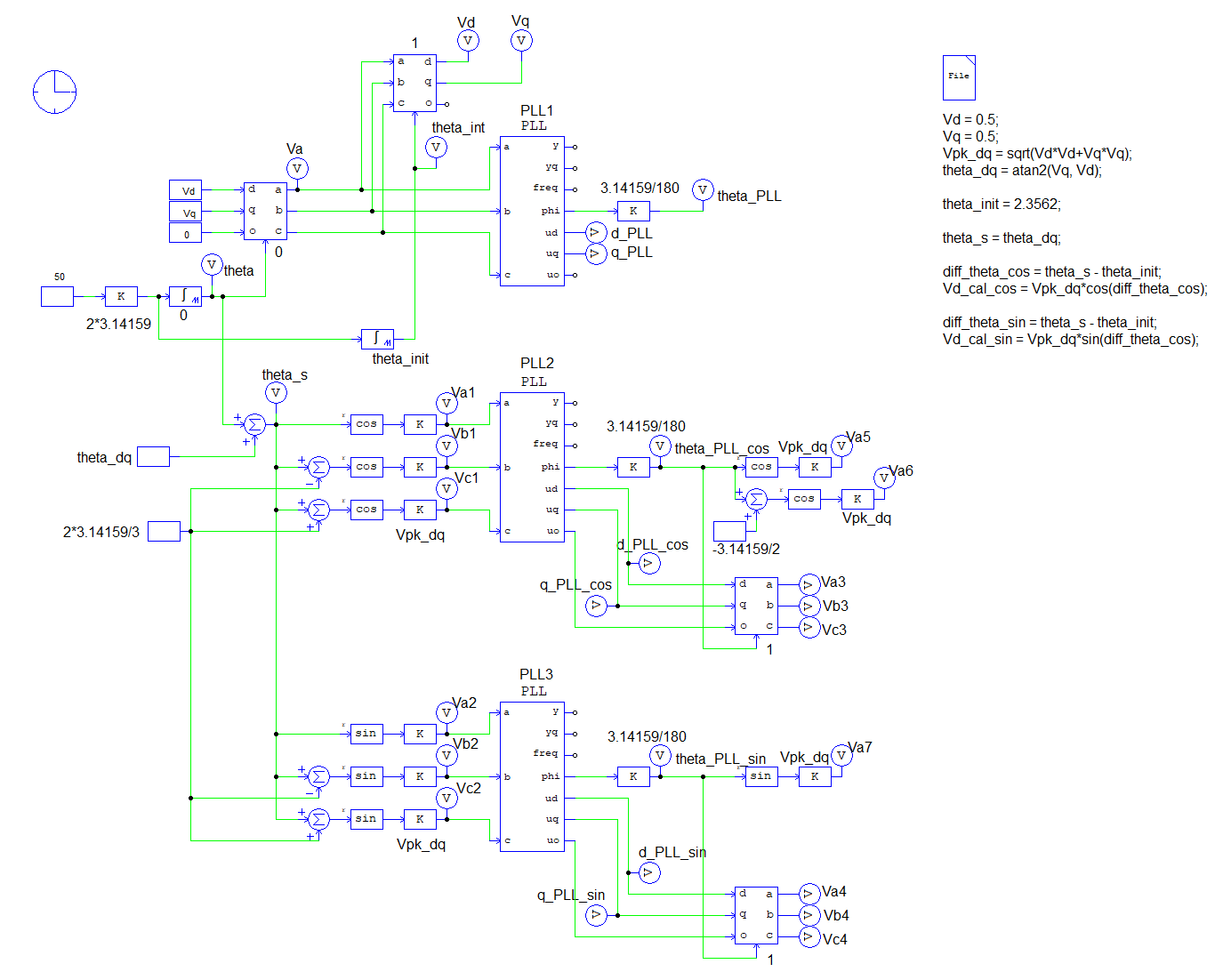
In the test circuit, for the purpose of generality, I used Vd=0.5 and Vq=0.5 to generate the 3ph signals. The same conclusions apply to other Vd and Vq settings.The test circuit has 3 PLL blocks: PLL1, PLL2, and PLL3. PLL1 is the same as what the customer sets up. The PLL2 circuit is the same as the PLL1 circuit in functionality.
The difference is that Vabc are generated manually instead of using the dqo/abc block. The PLL3 circuit uses the sine function based Vabc as the inputs to the PLL block.
The expectation was that, in PLL1, theta_PLL should be the same as theta, and d_PLL and q_PLL should be the same as vd and vq.That's actually not correct due to two reasons:
The first reason is that when dqo is converted to abc, there is an additional phase angle that needs to be considered due to the dq quantities. Let me explain. For ado/abc transformation:
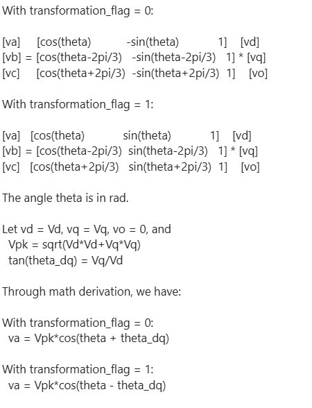
This means that an additional angle, theta_dq, needs to be added to Vabc. This also shows that the 3-phase abc outputs from the dqo/abc block are based on the cosine function. This is important as it will be shown later.
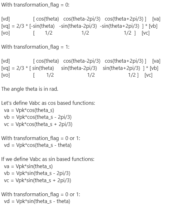
Now let's consider the abc/dqo conversion block.
The second reason why the expectation was not correct is because of the way the PLL block works. Internally, the PLL block uses an abc/dqo block with transformation_flag = 1, and it has a PI control loop that tries to achieve vd to be 0, as shown from the block diagram above. This is why the d-axis value of the PLL output always converges to 0 eventually.
In order to achieve vd = 0 of the internal abc/dqo block, with transformation_flag = 1, using the expression vd = Vpk*cos(theta_s - theta), it means that the phase difference (theta_s - theta) must be +/- 90 deg. In the test circuit, it means that theta_PLL_cos and theta_s should be 90 deg. apart. This is what the simulation result shows. This is where the difference of 90 deg comes from.
In this test case with Vd = 0.5 and Vq = 0.5, theta_dq = 45 deg. In another word, the phase difference between theta_PLL_cos and the original theta (that is used for dqo/abc transformation) is 135 deg. (i.e. 90+45). To confirm, if we set theta_init = 135 deg., we get Vd = 0, and Va = Va1 = Va6 = Va3. However, if you use theta_PLL_cos directly with a cos block to generate va, you will get Va5 which is incorrect as theta_PLL_cos and theta_s are supposed to be 90 deg apart.
If one really wants to get rid of the 90 deg. difference, one can use the sine based functions as shown in the PLL3 circuit. If Vabc are sine based, vd = Vpk*sin(theta_s - theta). For vd = 0, theta_PLL will be the same as theta_s. In the simulation, Va2 = Va7 = Va4.
Feel free to find and test the example attached.