The Siemens Community Catalyst program was co-created with our community to acknowledge technology leaders who consistently contribute to the Siemens Community. Nominations are accepted on a rolling basis.
Hello members,
I want to run this simulation of infinite ground and substrate of probe-fed patch antenna, but it is taking more than two days, and still, 0% of the simulation is done. Please kindly tell me how I can run this model faster.
Hi @sswh2,
Not sure what the problem is, but I would recommend defining the structure above the infinite PEC, not below. Please have a look at attached model infinite_square_ground_aps_patch_alt.cfx.
Simulation takes a few seconds.
Best regards, Torben
Hi @sswh2 ,
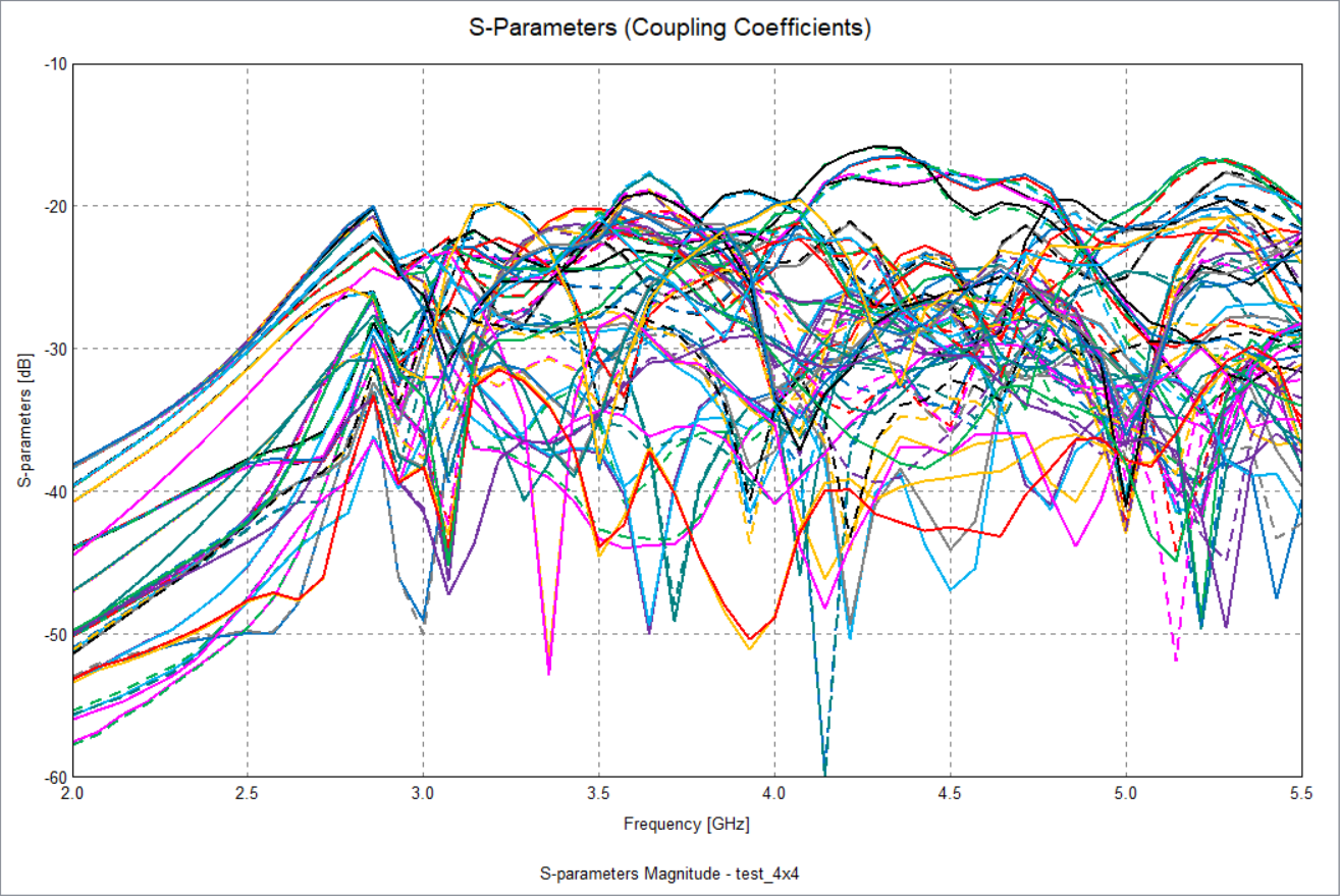
Maybe I misunderstood something, but why don't you just use a SParameterConfiguration, as in the attached model?
In POSTFEKO you can then plot whatever you're interested in. Here for example all the coupling coefficients:
Does this help?
@sswh2 I didn't change the wire radius and just checked again: The wire radius is 0.65 mm:
I almost forgot:
ERROR 33564: Waveguide ports and a special Green's function are not allowed simultaneously
So, since you can't use waveguide ports, you could use a wireport instead:
Model is attached.
@Torben Voigt Sir thanks a lot!! The simulation just finished. It's working
@Torben Voigt sir, thanks. How to check F-parameter in Feko in cases of array? we have that option to choose sequential port in CST, but how to check F parameter in FEKO?
Could you please explain what exactly F-parameters are in CST? A quick Google search brought up this:
"F-parameters are used to calculate antenna coupling coefficients between nearfield or farfield sources. If a field source is not activated, only receiving coupling coefficients will be computed for that source. However, this option is only available for simultaneous field source excitation." (https://electronics.stackexchange.com/questions/418110/f-parameters-instead-of-s-parameters)
To calculate the S-parameters of an array in Feko, it probably depends on how the array is calculated. Are you using the Finite Array Tool? Or do you use PBC? Or are you modeling it in the classic way (with X x Y elements, each with port)?
Actually, I could only say in the latter case that you can simply determine the s-parameters. For Finite Array Tool and PBC it might be more difficult. Do you have an example?
@Torben Voigt sir yes i am doing infinite ground plane patch antenna array, so each element has different ports, I need the active ports so that I don't have multiple s11 , like s11, s21, s31, s41. I dont need multple s11, its called sequential excitement in ports in CST so that we can get one s11 curve which will show the effect of all elements inside the array, I want to know this excitation opion in FEKO. Here is my model attached
@sswh2 , I would like to know how large the array should be, because it would be advantageous not to use the Finite Array Tool to calculate the s-parameters. Can you tell me the desired number of elements?
@Torben Voigt the size should be 4 by 4. I tried without finite element array , but different ports are giving me multiple s11, i need one s11, thiat is called active excitation , how can i do that? kindly tell me the option, that works in cst using sequential excitation which is Fparameter,
@Torben Voigt sir thanks!! its helping. Ijust changed the option to unit magnitude convention under the S parameter tab, now its giving me one single s11 curve which I wanted, but can you make this file with my wire radius 0.65 mm, the file I attached had wire radius 0.65 mm can you make this in this 4 by 4 file?
@Torben Voigt sir thanks!! its running, can you kindly check this model and fix the error it is simple single patch with coaxial probe and infinite ground plane, somehow it is giving error that probe outer conductor media is intersecting with dielectric layer, can you kindly fix this?
Hi @sswh2, the problem is that the infinite PEC plane is blocking the waveguide:
A quick workaround could be to extend the waveguide slightly so that it protrudes into the dielectric layer. Then you could apply "Planar Green's function aperture" to the interface of the Teflon, so that it is no longer PEC:
But I have to test it.
@Torben Voigt sir I tried by increasing a bit thent it is giving error that the face of the outer conductor is intersecting with the multi layer, this method is not workinG…the upper face of the outer conductor should be dielectric boundary , I did it accordingly FEKO tutorial for coaxial probe, but in case of multilayer this techniques is giving me error..
If I were you, I would do without the planar Green's functions (infinite layers). They are a powerful tool to simulate simple structures or radome layers very quickly, but as soon as the number of mesh elements increases, the efficiency decreases. Since I assume that you will again form an array with this model, I would really recommend finite dielectric.
@Torben Voigt sir, no my work is to check with infinite ground plane so I can't use the finite ground structure for coaxial probe feeding. Thanks for your reply again.
You could use an infinite dielectric layer but deactivate the infinite PEC ground. Then you could use a finite PEC ground.
@Torben Voigt I can't do that; my goal is to investigate the effect of infinite ground, so in FEKO, this multilayer is the only option. Thanks.
Happy to hear! :)