
INTRODUCTION
Hydraulic lift gates are used for loading and unloading goods into trucks, making it easier for drivers to transport heavy goods. Optimizing performance and efficiency is crucial for staying ahead in hydraulic lift gate design. This article explores how engineers can utilize multibody dynamics (MBD) and optimization to transform their design processes. By leveraging Altair Inspire's integrated MBD and optimization capabilities, engineers can simulate and refine hydraulic lift gate design to lightweight components and save on material costs. Beyond optimization, analysis tools allow engineers to develop hydraulic actuator specifications by predicting the forces required by the linear actuators.
In this example, we will build a model of a hydraulic lift gate in Inspire. Inspire is an integrated simulation environment that enables faster decision making by design engineers and CAE analysts. Foregoing the traditional “pre-process - solve - post-process” cycle prevalent in traditional CAE software, it can perform all 3 functions in a single environment. Inspire’s CAD integration, semi-automated MBD model build, and structural solver integration help to considerably flatten the learning curve. An engineer can perform a motion analysis, extract loads to perform FEA, and then optimize components all in one environment. We follow this workflow to make a hydraulic lift gate move a pallet into a truck, and then we will optimize a critical link to minimize weight and save material.
Understanding the Model
Building the Motion Model
- Geometry was imported into Inspire.
- Joints were created between each component.
- Actuators with displacement vs time curves are used to control lift and tilt actuators.
- A pallet with a mass of 750 kg was placed on the lift.
- Contacts were built between the pallet, lift platform, and rails.
- A motion analysis was performed to review the lift’s motion.

Optimizing the Support Link
- The support link was partitioned where it is connected to joints.
- The link and partitioned sections were added to a rigid group.
- The support link was made into a design space.
- Shape controls were added to ensure the optimized part is symmetrical.
- Draw direction controls were added to create a part that can be cast or machined.
- The part was optimized with the goal of minimizing deflection and a target of 30% the initial mass.

Design Space – 133.8 kg Optimized Part – 51.2 kg
SOFTWARE REQUIREMENTS
Inspire (2024 or newer)
MODEL FILES
MODEL SETUP & SIMULATION STEPS
- Open Lift_Gate_Baseline.stmod or Lift_Gate_Optimized.stmod in Inspire.
- Perform a motion analysis.
- Use analyze part to compute the stresses on the support link.
RESULTS

Hydraulic Lift Gate Motion


Baseline Link Stresses
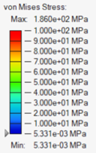

Optimized Link Stresses

Peak Stresses During Motion
The baseline link experienced stresses up to 143 MPa while lifting a 750 kg pallet. After optimizing the link, maximum stress increased to 186 MPa. These stresses are well below the 400-600 MPa yield strength of high strength steel alloys. The mass of the link decreased from 133.8 kg to 51.2 kg, a decrease in mass of ~62%.
The actuators utilize displacement over time profiles to move and tilt the platform. Inspire calculates the force required to achieve these motion profiles. The required actuator force can be plotted and used to select hydraulic actuators capable of lifting the hydraulic gate’s design load. One important observation with this lift gate design is the tilt actuator requires a high force to prevent the platform from tilting


CONCLUSION
In this example, we optimized a hydraulic lift gate link, achieving a mass reduction of 62% while maintaining the lift’s load-bearing capacity. By extracting load data directly from a detailed motion analysis, we ensured that the optimization process was based on realistic conditions, enhancing the accuracy of the results. The ability to build geometry, perform FEA, run a motion analysis, optimize parts, and review results in one environment makes Inspire a powerful tool for designers and engineers looking for a streamlined workflow that results in better designs.
AUTHORS
John Dagg, Systems Engineering Intern
Christopher Fadanelli, Solution Engineer – Systems Integration
Ananth Kamath Kota, Global Technical Manager – Systems Integration
