It is widely known that in every powertrain system, the motor shaft is connected to a gearbox in order to increase the Torque by reducing the revolutions per minute. In PSIM, there is a block that simulates a gearbox but it has a fixed gearbox ratio. For that reason, this article focuses on presenting a gearbox with a lot of gear ratios, like the gearbox of a hybrid car.
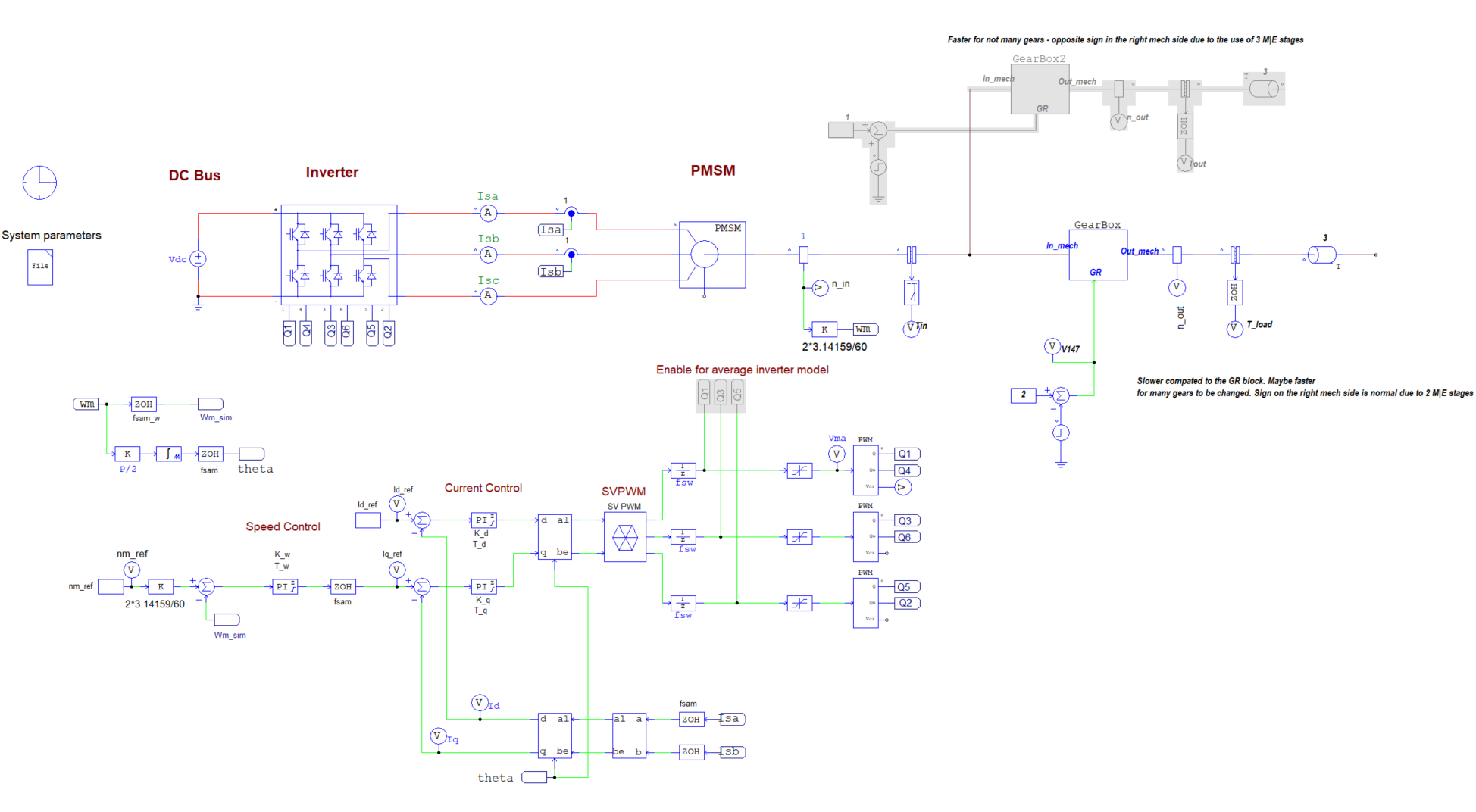
Hybrid cars feature gearboxes with either discrete gear ratios or continuous gear ratios.
Discrete Gear Ratios
Continuous Gear Ratios
Discrete Gear Ratios
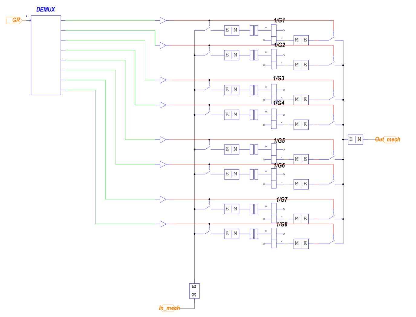
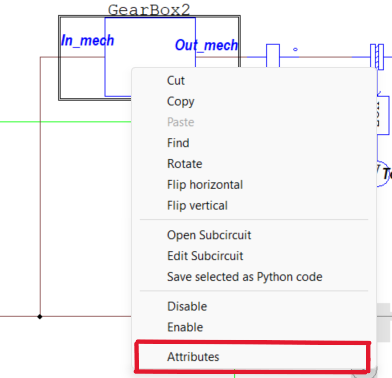
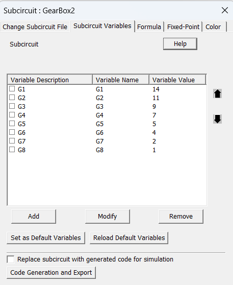
Depending on the Gearbox relation that is selected, the DEMUX sends a signal only to the corresponding gear ratio. In order to change the gear ratios you have to right click at the gearbox block and select ‘Attributes’
Labels:
GR: Gearbox relation (for example 1,2,3 etc) In_mech: Input mechanical connection Out_mech: Output mechanical connection
Note: Do not confuse the gear relation with the gear ratio. The gear ratio should be defined by you as referred above.
Continuous Gear ratios
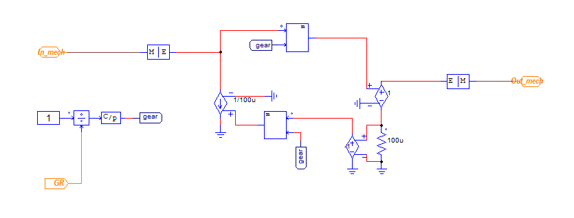
The primary distinction of this gearbox is its ability to have a continuous gear ratio, and not necessarily a discrete one. The shown schematic, is an ideal transformer and the mechanical/electrical connection converts torque to current and speed to voltage, allowing this topology to divide voltage(speed) and multiply current(torque) according to the gear ratio.
At this gearbox the GR label refers to the gear ratio used.
Torque measurement
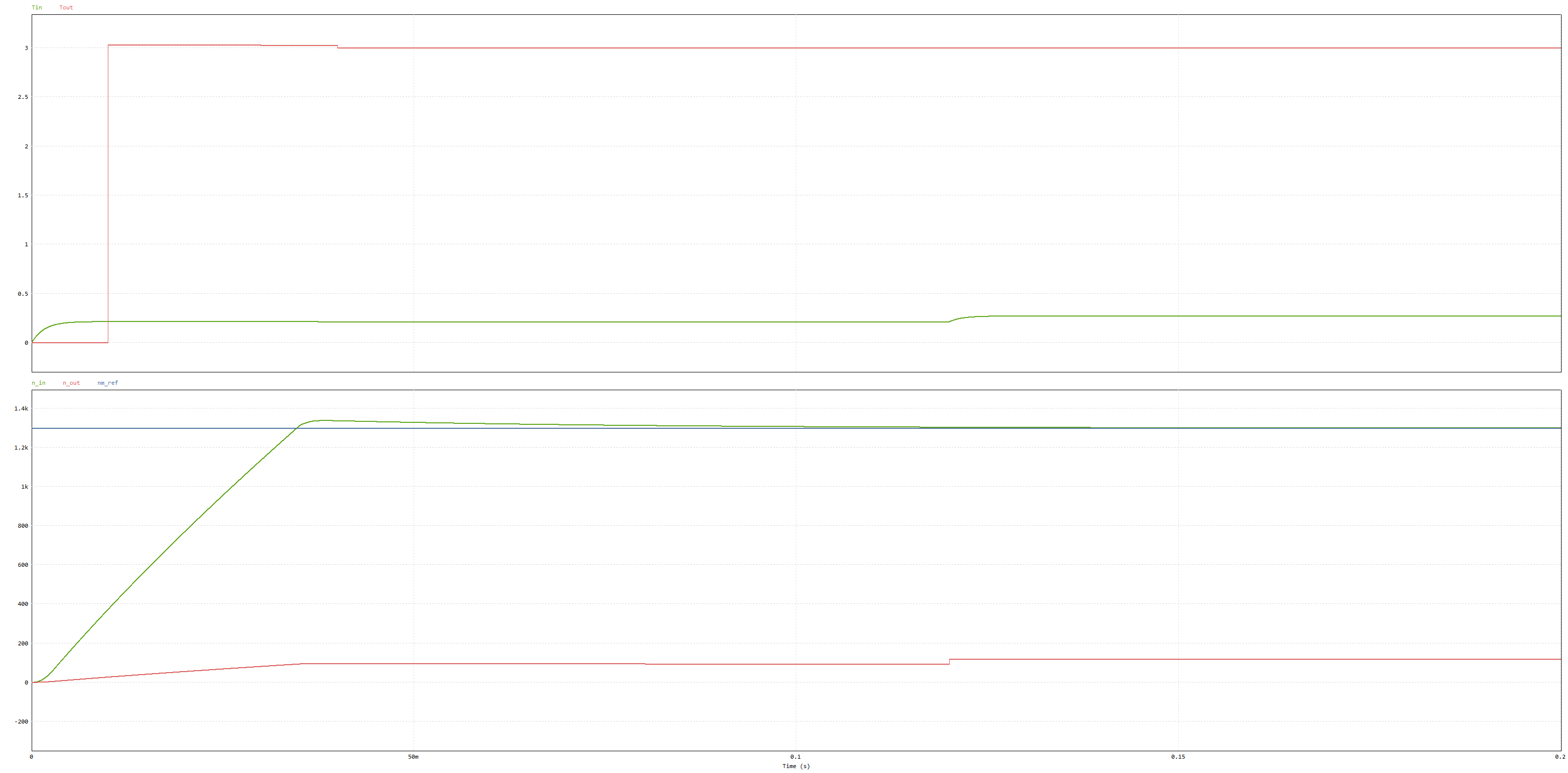
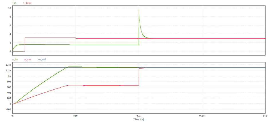
Due to the instantaneous gear relation change, we observe undesirable oscillations. For this reason we use the ‘Zero-Order Hold’ block to adjust the sampling frequency of the Torque measurement (100 Hz)
Conclusions
For a small number of discrete gear ratios, the first gearbox is preferable due to faster simulation times. Conversely, if the gearbox has numerous gear ratios, the second gearbox is more suitable. Additionally, for simulating a continuous variable transmission, the second gearbox is the appropriate choice.
Project file