Shell & Solid Composite Modelling Different Behaviour

Turbokraken
Turbokraken Altair Community Member
edited October 2020 in Community Q&A

Dear Everyone,


I am have been working with the shell modelling of composites, using the PCOMP-card and plies and laminate definition. I wanted to take it to the next step and try the modelling of composites using 3D elements. I have looked into the Shell to Solid Conversion of HyperMesh first and then started on my own using the PCOMPLS card. I modelled the exact same plate twice to see if I can re-do my 2D results in 3D. However I came to find that both results are vastly different.


Do you know how this could happen? Displacement of 111 vs. 37...

I have attached both of my files, could any one of you please have a quick check?


Any help would be greatly appreciated!


Best Regards,

Lennart

<?xml version="1.0" encoding="UTF-8"?>fghfghgfh.png

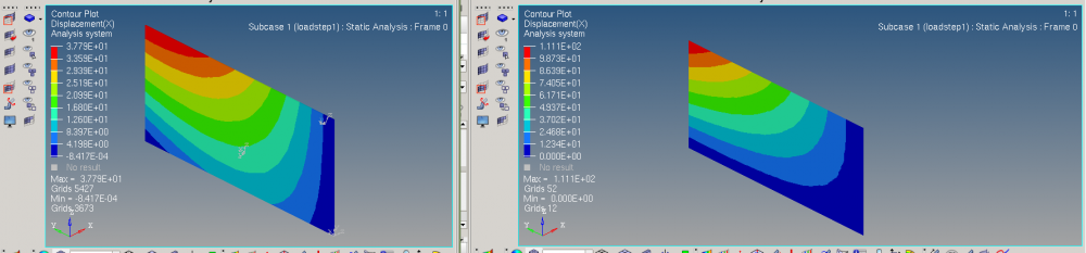
Unable to find an attachment - read this blog

Welcome!

It looks like you're new here. Sign in or register to get started.

Answers

  • Rahul Rajan_21763
    Rahul Rajan_21763 New Altair Community Member
    edited February 2019

    Please find below some suggestion from my colleagues:

    1.Make sure you convert MAT8 to MAT9 (or MAT9ORT) correctly.  I always get messed up with v31 (OptiStruct MAT9ORT input) which is NOT equal to v13 (Typical value users have).  I’ve done a few studies between PCOMP/G, PCOMPLS, and PSOLID and I get “reasonable” match….but admittedly I have not done a conclusive test.  Also, double check your BCs…you have a few more nodes in PCOMPLS vs PCOMP/G that you have to get right between the two models. Just giving some guesses from my experiences.


    2.The solid shell has a thickness direction that needs to be defined properly. Take hex8 for example, grids 1 2 3 4 lie on bottom of the shell and 5 6 7 8 lies on the top of the shell.

  • Turbokraken
    Turbokraken Altair Community Member
    edited February 2019

    Dear Rahul,


    thank you very much for your answer.

    I still could not resolve the issue, even with reviewed material constants. Could you elaborate on what you mean with my BCs? (I assume you mean SPC?) I do have free nodes there but those where just for designing the part.


    BR,

    Lennart

  • Rahul Rajan_21763
    Rahul Rajan_21763 New Altair Community Member
    edited February 2019

    Yes I mean SPC constraints.Developement team suggested me to test shared file in internal beta build of 2019 version which yield closer with 2d & 3d element.

    There are some changes after 2018 which affect the results.

Welcome!

It looks like you're new here. Sign in or register to get started.

Welcome!

It looks like you're new here. Sign in or register to get started.