Cables are flexible structures that support applied transverse loads by the tensile resistance developed in its members. An element can be considered as a cable when it allows only tensile and no compressive forces to be carried through it. In Optistruct CGAP, CBUSH, JOINTG elements with PGAP, PBUSHT, PJOINTG properties respectively, can resemble this behavior and be used as cables.
To capture the cable behavior a Nonlinear Analysis must be performed. (Nonlinear Implicit Static/Transient)
1. CGAP Cable
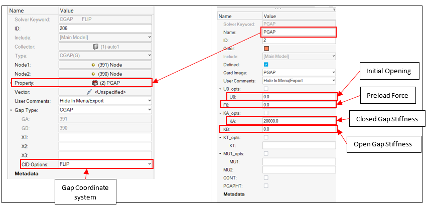
A CGAP element with a PGAP property can be used to represent a simple cable element. This can be done by reversing the default gap orientation and defining the pre-existing "slack" or extra length in the cable (initial gap opening U0).
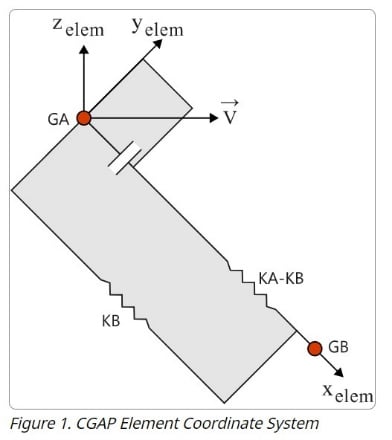
The gap element coordinate system is defined In the CGAP card by one of the following methods: CID, blank, or FLIP
CID: If the coordinate system CID is specified, the element coordinate system is established using that local coordinate system.
CID field blank: If the CID field is blank and the grid points GA and GB are not coincident (distance GA -GB > 10-4), the line GA-GB is the element x-axis, and the orientation vector lies in the x-y plane.
FLIP option: the x-axis of the gap coordinate system is reversed with respect to the default orientation described above.
By setting the CID=FLIP the x-axis of the gap’s coordinate system is reversed with respect to the default orientation. In this case, gap’s "open" status will correspond to the cable being "shortened" (no tension), while "closed" will correspond to the cable being "elongated" (in tension).
The same can be achieved by defining a local coordinate system for the Gap element, where the x-axis will be reversed with respect to the default orientation. This is applicable only when grids GA & GB coincide (distance GA-GB < 10-4).
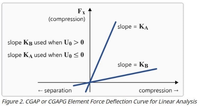
In the PGAP card two stiffness values can be defined KA and KB, where KA is the axial stiffness for the closed gap and KB is the axial stiffness for the open gap. The gap element force-displacement behavior is different in linear and nonlinear analysis. In linear analysis, the gap stiffness is constant and depends on the initial gap opening U0. If U0>0 the stiffness is defined by KB slope and if U0≤0 is defined by KA slope. In nonlinear analysis while the gap is open, the stiffness is defined by KB slope and when the relative displacement (UA – UB) becomes equal to the initial opening (U0), the gap closes, and the stiffness is defined by KA slope.
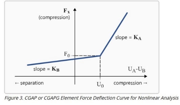
In the PGAP card, preloading can be included via F0 field which corresponds to a pair of forces acting on the ends of the cable (pointing inwards).
Example:
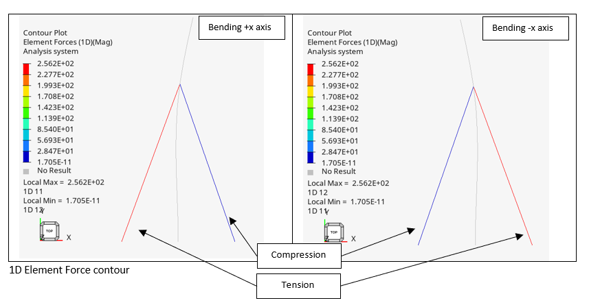
The following is a nonlinear static example of a mast undergoing bending, where we define 2 cables with CGAP, PGAP and stiffness only for the closed gap (tension when using the FLIP option).
2)This is the same example where we also apply a preloading force (F0) to the cables.
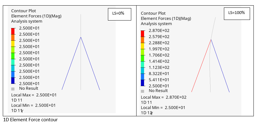
The cable that experiences compression retains the preloading force after the loading.
2. CBUSH Cable
A nonlinear cable can be modelled using a CBUSH element with PBUSH&PBUSHT properties which define a generalized spring-damper structural element.


The element’s orientation can be defined using a vector (X1, X2, X3) or GO or a local coordinate system CID in the CBUSH card.
When GO or (X1, X2, X3) is given and no CID is specified, the line AB is the element x-axis and the orientation vector v̅ lies in the x-y plane. If CID > 0 is given, then it overrides GO and Xi. The element x-axis is along T1, the element y-axis is along T2, and the element z-axis is along T3 of the CID coordinate system.
In the PBUSHT property card, by activating the KN line, different force vs relative displacement (UA-UB) curves can be defined for each of the six degrees of freedom. Tension happens when U > 0 and Compression when U < 0, where U = U(GB) - U(GA), in the CBUSH element coordinate system (GA/GB are grid points of the CBUSH).
A cable can be also modelled with an one-dimensional spring-damper element CBUSH1D, where the nonlinear properties of the element can be provided with the PBUSH1D property card. There a force vs relative displacement (UA-UB) curve can be defined, representing the cable stiffness in tension and compression.
Example:
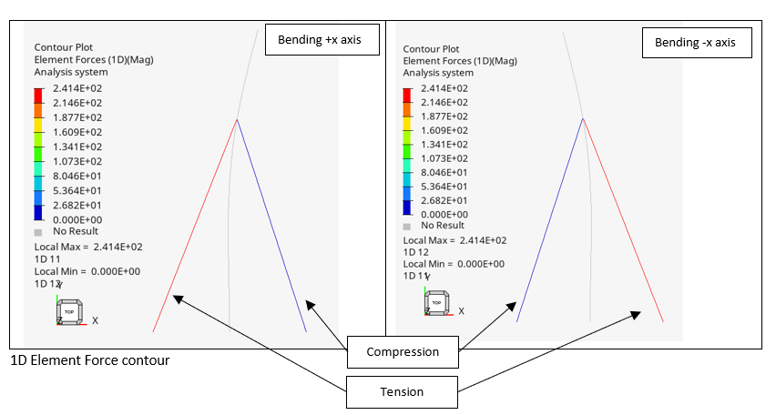
The following is a nonlinear static example of a mast undergoing bending, where we define 2 cables with CBUSH1D, PBUSH1D and stiffness only under tension.

3. JOINTG cable
A nonlinear cable can be modelled using an axial JOINTG element with PJOINTG properties which define a joint connection between two grid points.
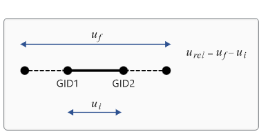
An axial JOINTG element is a joint which allows connection between two grid points by enforcing relative displacement along the line joining them. The relative displacement is enforced only along the line connecting the two grid points, and other degrees of freedom are not constrained by this joint. Typically for a particular degree of freedom, the relative displacement is calculated as:
u_rel=u_GID2-u_GID1
Where uGID1 and uGID2 are displacements of GID1 and GID2 in a particular degree of freedom.
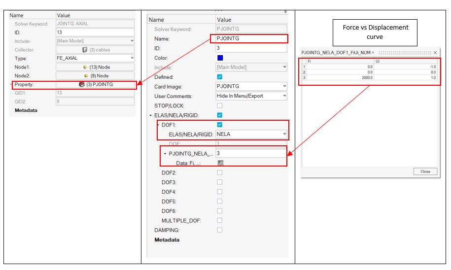
In the PJOINTG property card for nonlinear elastic type properties (NELA), a force-displacement curve can be assigned to each degree of freedom associated with the joint. The degrees of freedom are listed in the DOF field and the corresponding force-displacement curve values can be specified on the Fi and Ui fields.
Example:
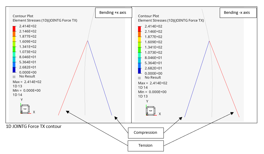
The following is a nonlinear static example of a mast undergoing bending, where we define 2 cables with JOINTG, PJOINTG and stiffness only under tension.
4. SLIPRING JOINTG:
From Optistruct Version 2024 a new JOINTG element was introduced named SLIPRING joint. SLIPRING is supported only for implicit large displacement nonlinear analysis and explicit dynamic analysis.
The SLIPRING joint is a special JOINTG element designed for modeling systems that involve cable or wire rope movement over pulleys. Typical applications include lifting mechanisms, horizontal pulling systems, seat belts, and scenarios involving continuous material flow. This joint supports only one degree of freedom (DOF = 1), and the slipring angle is determined geometrically, based on the configuration of the connected elements. Friction and mass properties can also be defined through the associated PROPERTY entries.
An additional degree of freedom, referred to as flow, is accounted with SPOINTs, which are explicitly specified in the continuation line of the JOINTG entry. SPC entries are used to constrain flow on these SPOINTs as needed. By default, flow is enabled unless explicitly constrained.
Slipring is discretized point wise and it requires, as a minimum, two elements in series where they share a common node. Slipring elements are defined with two grids and property, no system (similar to the axial JOINTG).
In the PJOINTG card the bellow properties are available for SLIPRING joints:
ELAS - For stiffness defined for SLIPRING joints, the specified value is in units of force (not force/length). The value of stiffness is internally adjusted based on the corresponding rope length during the analysis.
NELA - Defined as Force vs Strain table.
Friction - coefficient (optional) for frictional sliding problems.
MASS - of the rope as mass per unit length.
Example:
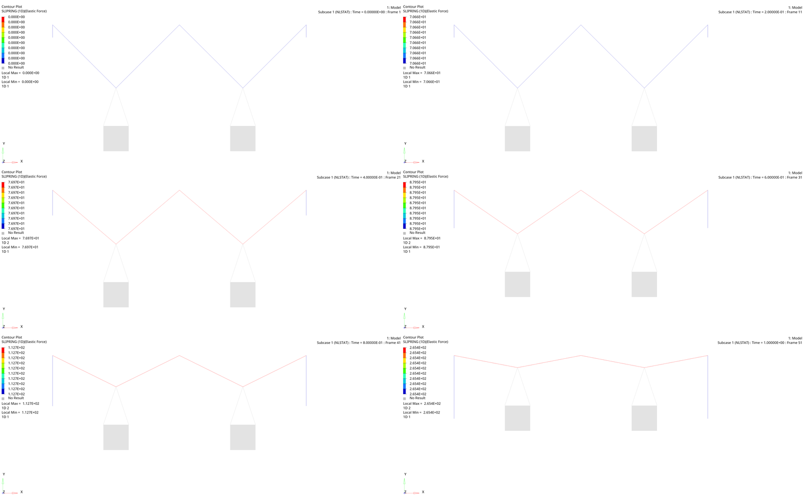
The following is a nonlinear static example of a frictionless multi-pulley system. Two weights, 100.0 each, are lifted using enforced displacement at both ends of the Slipring chain (6 slipring JOINTG elements).


Slipring elements definition in .fem file:
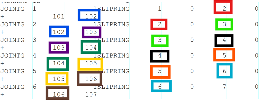
Two zero SPC will be added at the two ends of the slipring chain to constrain the mass flow. The SPCs should reference the two SPOINTs at the end ID=101 and ID=107

