In Altair Radioss, it is possible to define multiple engine files (e.g. _0001.rad, _0002.rad,…). This capability is a powerful feature, and some common applications include:
- Pre-tension or initializing gravity before a simulation.
- Changing the time step control options used.
- Turning on and off rigid bodies.
- Changing the write frequency of output files, such as animation (/ANIM/DT, /H3D/DT) and time history (/TFILE).
- Add or remove boundary conditions.
How to remove a boundary condition during calculation
We will use a simple model with two shell elements connected by a spring element to show how to add and remove a boundary condition during calculation.
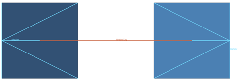
To remove the BCS during calculation, we should use multiple engine files and an engine keyword called /BCSR. These are the BCSR cards available:
- BCSR/TRA – Given node numbers will be released in specified directions X, Y, or Z for material translational DOF.
- BCSR/ROT – Given node numbers will be released in specified directions X, Y, or Z for rotational DOF.
- BCSR/LAG – Given node numbers will no longer be Lagrangian in specified directions X, Y, or Z.
- BCSR/ALE – Given node numbers will be released in specified directions X, Y, or Z for grid DOF.
The simulation is going to be divided into two steps. In the first step, an initial velocity will be applied to the right element while the left element is constrained.
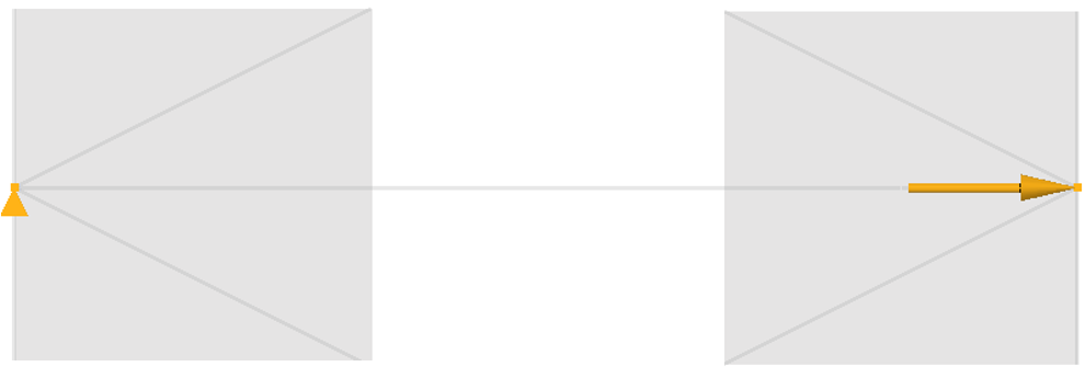
Engine file for the first step:
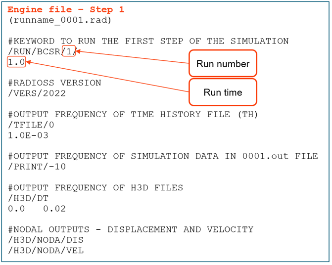
First step animation:

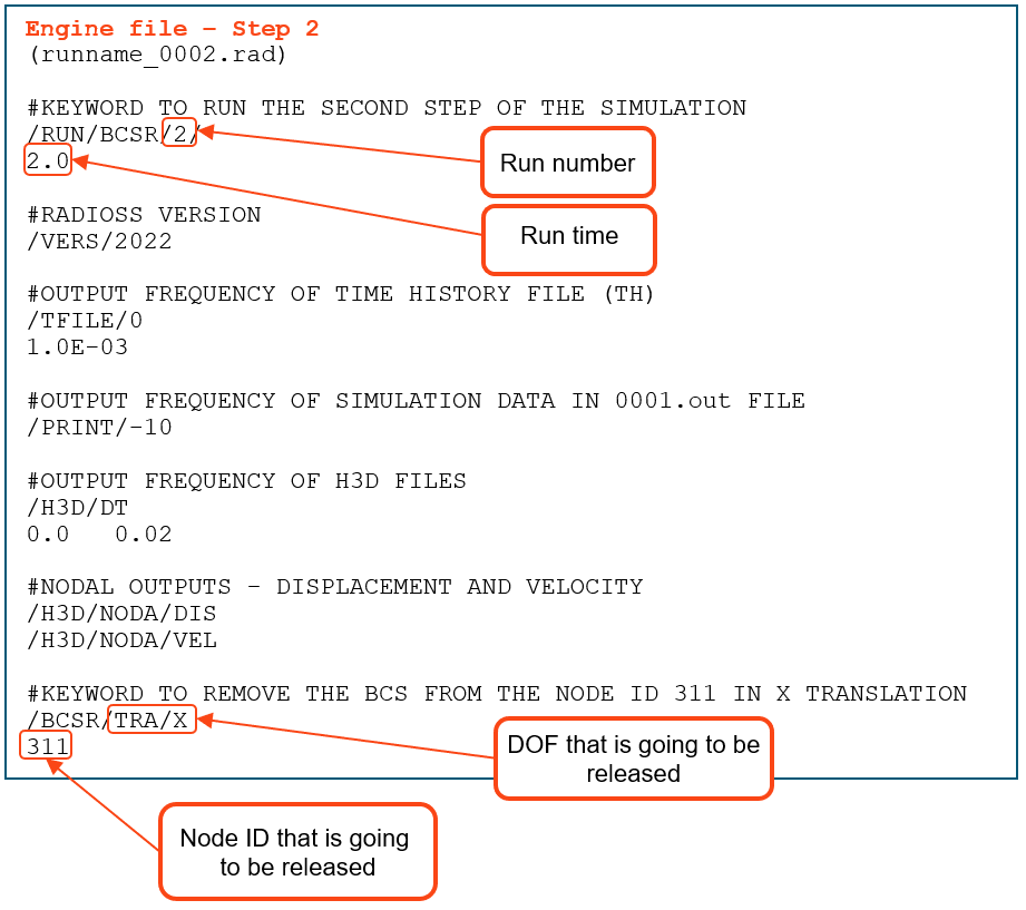
After the results from the first step, we will create the second step of the simulation. To do this, we are going to create the second engine file with the following changes:
- Copy and paste all keywords from the first engine file (in this step, if you want, you can also change the animation frequency, time step control, or turn a rigid body on and off).
- Rename it to runname_0002.rad.
- Change the run number to 2 on the /RUN keyword.
- Increase the run time to 2 (specific for this model).
- Add the /BCSR keyword, as shown in the image below.
Full simulation animation:

As you can see, when the simulation changes from step 1 to step 2, the BCS of the left element is released, and it starts moving due to the spring force.
The model can be downloaded here: BCSR_Model
How to add a constraint during simulation
To show how to add a constraint during the simulation, we will use the same model as before, but this time we will remove the constraint on the left element during the first step.
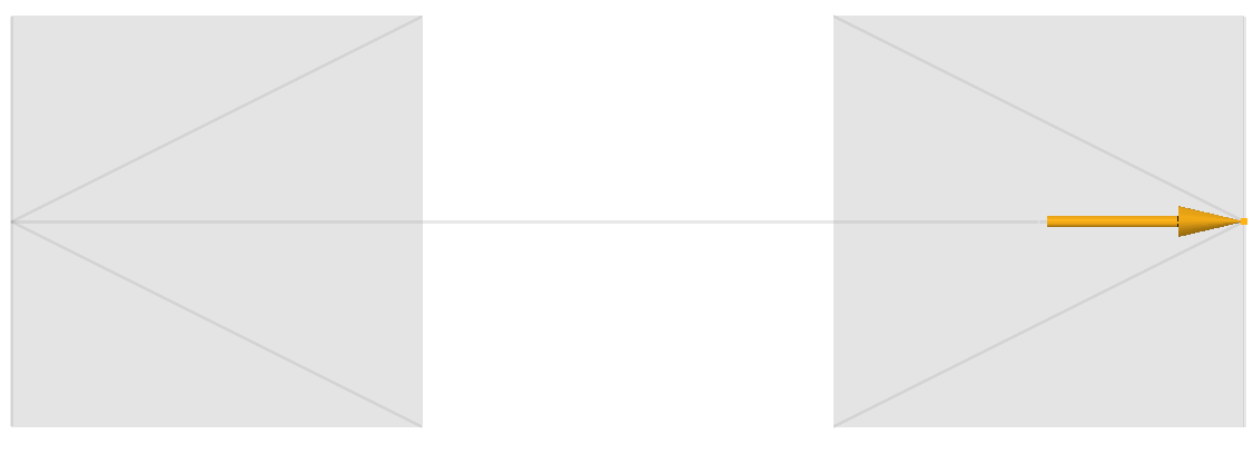
To add the BCS during calculation, we should use multiple engine files and an engine keyword called /BCS. These are the BCS cards available:
- BCS/TRA – Given node numbers will be constrained in specified directions X, Y, or Z for material translational DOF.
- BCS/ROT – Given node numbers will be constrained in specified directions X, Y, or Z for rotational DOF.
- BCS/LAG – Given node numbers will be Lagrangian in specified directions X, Y, or Z.
- BCS/ALE – Given node numbers will be constrained in specified directions X, Y, or Z for grid DOF.
Multiple engine files are used to split the simulation into two steps. In the first step, an initial velocity is applied to the right element while the left element is free. In the second step, the left element is constrained.
Engine file for the first step:
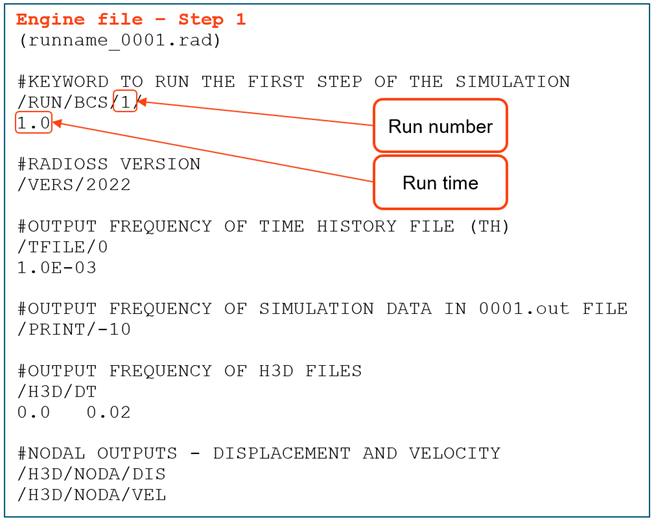
Animation for the first step:

After the result from the first step, we will create the second step of the simulation. To do this, we are going to create the second engine file with the following changes:
- Copy and paste all keywords from the first engine file (in this step, if you want, you can also change the animation frequency, time step control, or turn a rigid body on and off).
- Rename it to runname_0002.rad.
- Change the run number to 2 on the /RUN keyword.
- Increase the run time to 2 (specific for this model).
- Add the /BCS keyword as shown in the image below.
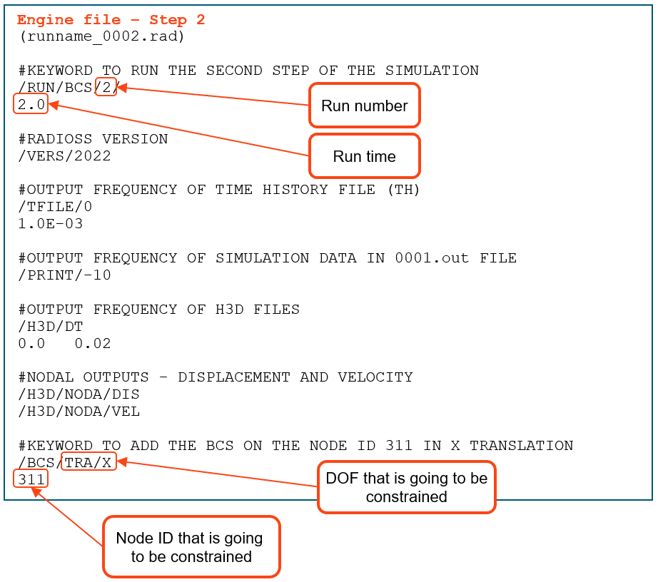
Full simulation animation:

As you can see, when the simulation changes from step 1 to step 2, the left element stops moving due to the /BCS added.
The model can be downloaded here: BCS_Model
More information about the engine keywords BCS and BCSR can be found here: Documentation BCS and BCSR
This article was originally created by Nobuyuki Fukuoka, and the Japanese version can be found here