Introduction
Purpose:
In the automotive and heavy equipment industries tire-soil contact area simulation is substantial in order to predict Tractor performance at Field applications (e.g. Puddling). Analysis can include the behaviour of tractor tires w.r.t traction, slip, drawbar power. Increasing the contact area would lead to increased traction and decreased ground pressure due to the weight on the tire being spread out over a larger area hence reducing tire sinkage and ground compaction. As contact area is dependent on a lot of parameters, like tire pressure, tire deformation, no. of lugs, lug spacing, lug profile, soil type, moisture content etc., Presently multiple field iterations (e.g. 10 or more design iterations) may be required to analyze the same, this requires lot of efforts, time and cost. Hence, using robust simulation model for will reduce the number of field iterations (e.g. 10 iterations to 3 iterations) and it is faster, reduces the efforts, also it gives the flexibility of varying a lot of design parameters to simulate RWUP (Real World Usage Profile) applications.
Functionality
This script has two main functionalities:
- Calculating the area of the tire geometry that is in contact with soil particles at each timestep in the simulation.
- Calculating the area of indentations in the soil for a given z slice at the last time step.
This document will give a brief overview of the inputs and methodologies for both calculations.
Tire Geometry Contact Area
This section of the script calculates the area of tire geometry that is contact with the soil.
This calculation is performed by retrieving the coordinates of all geometry mesh triangles that are in contact with a soil particle. The area of all the triangles that contain only these coordinates is then calculated. This means that a triangle could be included within the area calculation without being in contact with a soil particle if it is surrounded by triangles that are in contact with the soil. The calculation was done this way because it fills in gaps in the mesh that would be in contact with the soil in the real-life situation but aren't in contact here because of the granularity of particles in the EDEM simulation.
This contact area can be calculated for either the whole tire area or for just the outer treads of the tire:

Highlight any geometry in contact with soil Only highlight sections of the outer tread in contact with the soil
The tire geometry is comprised of many triangular faces stitched together to create the tire’s surface. To calculate the area of the outer tread that is in contact with the soil the script must first create a list of the triangles that make up the outer tread of the tire. This list of triangles is calculated by filtering the full list of triangular faces down to only those triangles which meet specific criteria. The three criteria used are:
- Tread alignment cut-off (ranges from -1 to 1).
- Radius cut-off (ranges from 0 to 1).
- Tire width cut-off (width in meters).
The value for these criteria should be selected based on the specific tire geometry, or if the application requires different parts of the tire geometry to be included in the calculation.
For Example: If the tire had a full width of 0.2m and the application required calculating the full contact area of the tire excluding only the side wall that would mean using the values:
- Tread alignment cut-off = -1
- Radius cut-off = 0
- Tire width cut-off = 0.2 - 0.01 - 0.01 = 0.18 (Assuming that 0.01m is enough to filter out the side wall)
To help in the selection of these values the following sections describe how these cut-offs are used by the script:
Tread Alignment Cut-Off
This filtering process eliminates any faces that aren’t facing radially out from the tires center. This calculation is performed by dot product calculation of the faces normal and the vector from the tire’s center to the geometry face. The dot product is closer to 1 when the vectors align and closer to -1 when they don’t align.
The script accepts an input called “tire tread alignment cut-off”; this value determines the filtering of geometry face i.e. a value of 0.8 would remove any faces that had a dot product less than 0.8. To ignore this filtering method set the tread alignment cut-off to -1.
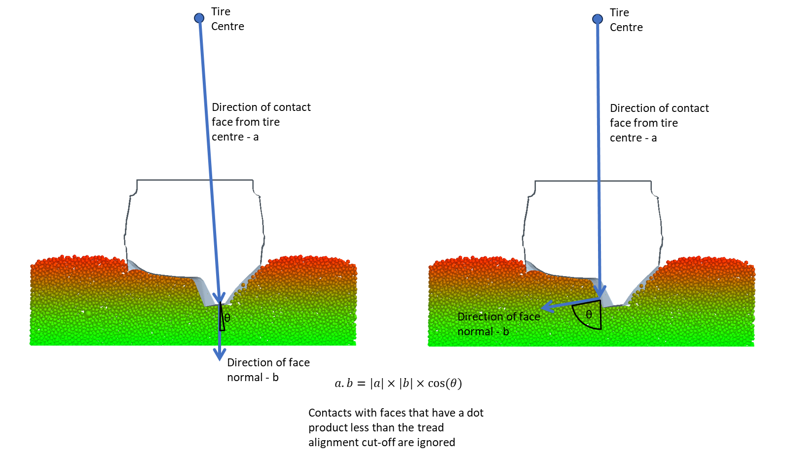
How tread alignment cut-off determines which section of the tire geometry to include.
Front on view of a tire to demonstrate how the tread alignment calculation works. The lefthand image shows how the face doesn’t point out from the tire, this would likely have a low value for the dot product and therefore be filtered out. The right-hand image shows that the face points out from the tires radius and would therefore likely have a high dot product value and not be filtered.

Tread Alignment Cut-Off specified under this heading the in the settings file.
Radius cut-off:
The method eliminates any faces that fall out with of a specified radial distance from the inmost section of tire to the outmost section of tire. This radial cut off fraction can be specified in the input file under the heading of Tread depth ratio cut-off, this value ranges from 0 to 1. A value of 0 would not filter out any tire geometry. A value of 1 would filter out all tire geometry. If the user only wants the outmost treads to be included in the area calculation, then they should specify a cut off radius that extends beyond the tire body, but is not greater than 1, testing has shown that 0.85 is a good starting point.
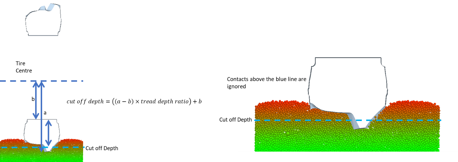
How radius cut-off determines which section of the tire geometry to include

Radius Cut-off specified under this heading the in the settings file.
Tire Width:
This filtering method eliminates any faces that fall out with of a specified distance from the centre line of the tire. This requires two inputs the axis of rotation of the tire and the width of tire excluding the side wall. The axis of rotation can be given as either x, y or z, and the width of the tire is given in meters.
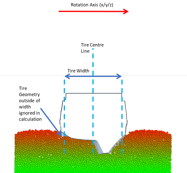
How tire width combined with rotation axis determines which section of the tire geometry to include.

Tire axis of rotation and Tire Width are specified in the settings text file under these headings.
Calculation Period:
The period over which this calculation is performed can be specified in the input file with the “Contact area calculation start time” and “Contact area calculation end time”. The sample rate can also be specified, and the script will only perform the contact area calculation every n time steps.

Settings for calculation period.
Outputs:
The geometry contact area is outputted for each timestep as the script performs the calculation but there are 3 additional optional outputs for the tire geometry contact area:
- Save a plot of contact area against time.
- 3D plot of the tire with geometry areas in contact with the soil highlighted in red (This is done for only 1 specified time step).
- Export a csv file with the contact area for each timestep in the form of a table.

Plot of contact area against time. 3D plot of the tire geometry.

Format of csv file exported by script.

Settings for script outputs in the setting file.
Tire Indentation area
This section of the script calculates the area of indentations that are left behind by the tire as it rolls across the soil. This calculation works by taking XY plane slices of soil and finding regions where there are no particles and identifies them as indentations in the soil.

Location of soil particles in an xy slice of the soil bed.

Regions of indentation identified and given an index.

Heatmap showing the area of each indentation.
This calculation is only performed at the last time step of the simulation as given in the settings file under the heading Contact area calculation end time.

The other 4 inputs for this part of the script are:

Soil Indent Area XY Bin Size:
This variable determines how fine of a grid is used to determine a filled or empty space in a specific slice of the soil bed. A grid space is empty if it contains no soil particle centers in that area, so the XY bin size should always be larger than the diameter of the particles otherwise particles can’t fit within a grid bin, creating empty spaces where there are none.
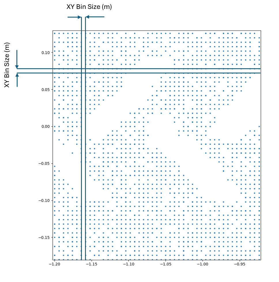
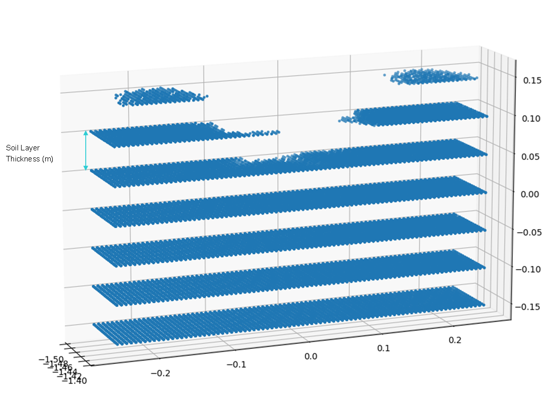
Soil Layer Thickness:
The soil layer thickness determines how thick each XY slice of the soil bed is. Similarly to the XY bin size the soil layer thickness should be larger the diameter of the particles.
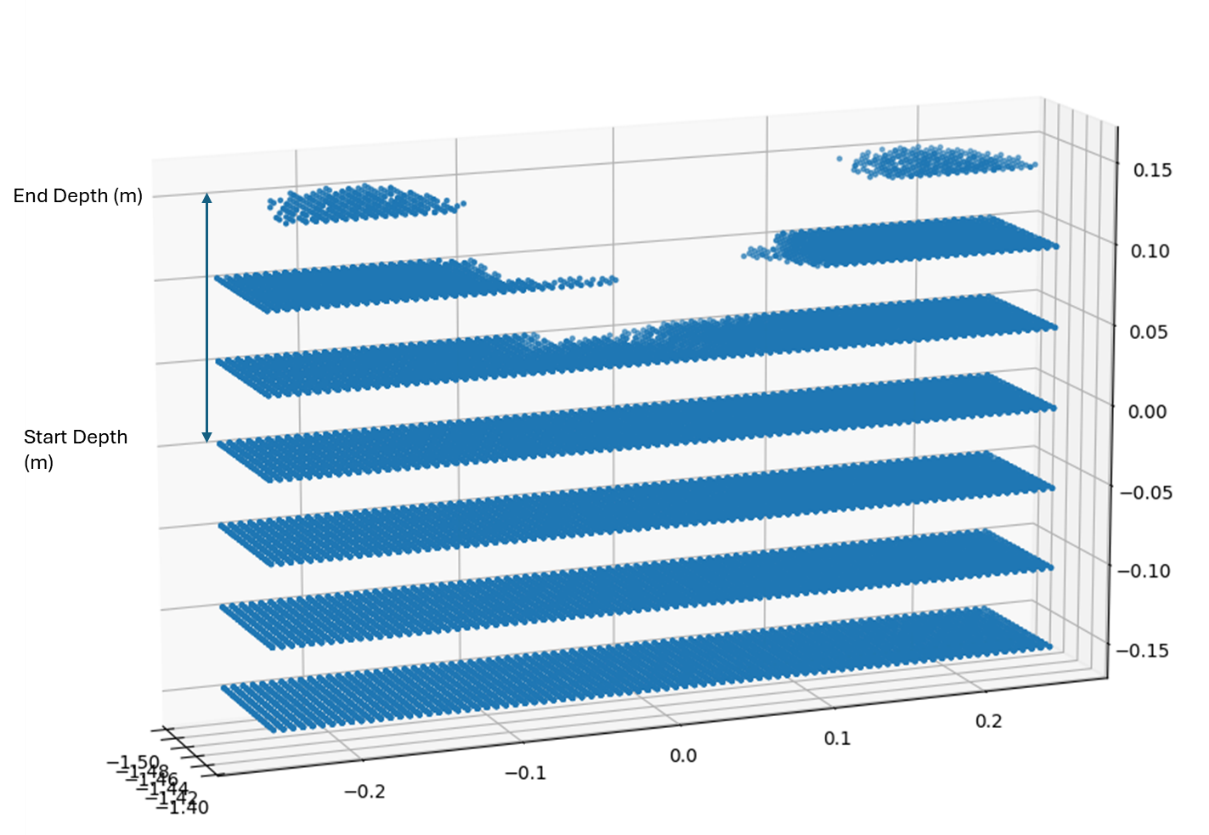
Start and End Depth of Indent Analysis:
These two variables determine the range of depths that the analysis would take place over. With the number of slices in this range being dependent on the soil layer thickness.
Outputs:
This section of the script has 3 main outputs:
- A plot showing the indented regions with an identifying number given to each region.
-
- A plot showing the indented regions where the color of each region correlates to the area of that indented region.
-
- A command line output showing the area of each region, the regions are identified by the identifying number shown in the first plot. This same data can also be exported to a CSV file by specifying in the settings file that a results report should be created.
Each of these outputs is generated for each slice of the soil bed.

Regions of indentation identified and given an index.

Heatmap showing the area of each indentation.

Command line output showing the area of each indentation.
Pre-Requisite
Have EDEM 2023.1 or later installed.
Have EDEMpy 1.4 installed.
Usage/Installation Instructions
Download the attached files. The zip file contains an optional test deck.
Launch the EDEM deck with the soil bed. Open the preference file and change the settings accordingly. Define the correct EDEM deck and tire geometry names, select the appropriate settings.
Go to the Analyst tab and click on File, Run EDEMpy script and select the script. Note that the deck and the script and preference file should be in the same folder. Run the script. A command prompt will open showing the results and check the folder for the output files.