Overview
Preface
Altair's MotionSolve is a powerful software tool for simulating and analyzing vehicle dynamics and performance. The Vehicle Tools Extension allows the User to easily assemble common vehicle platforms and simulate a wide range of vehicle events and maneuvers, such as lane changes, hill climbs, handling tests, and more.
In this current release it is quite simple to vary vehicle parameters to study the change in performance with respect to a consistent event, such as a Lane Change, J-Turn, or Road Course. This can be done using Altair HyperWorks or the internal Optimization Tool.

Altair HyperStudy Information Page: https://altair.com/hyperstudy
However, what if we wanted to keep the vehicle consistent but vary event type, speed, or size on a large scale? That type of feature would allow entry-level Users to run large Design of Experiments (DOE) to evaluate a vehicle's performance across a dynamic duty cycle. This tool could be reused for various vehicles regardless of the vehicle size or configuration. For that, a custom Compose GUI was developed to complete this dynamic Design of Experiments.
Altair Compose is a powerful environment for doing math calculations, manipulating, and visualizing data, programming, and debugging scripts useful for repeated computations and process automation. Compose can bridge the gap for unique cases like this one, and potentially contribute to functionality in future releases.
Usage/Installation Instructions
Introduction
In this article we solve a specific Customer issue in which an electric motorcycle model was to be put through a dynamic duty cycle for verification as a final design candidate. The vehicle model was developed using MotionView v2024.0 and a lengthy duty cycle was to be simulated for this model. A total of 9 events with varying speeds and sizes were desired to be run. However, the speeds and sizes of the events were potentially going to change rapidly throughout the development as the exact requirements were still being finalized.
The default motorcycle events to simulate can be found summarized below:
- Constant Radius
- U-Turn (Road Course)
- Slalom
- Since Lane Change
- Double Lane Change
- Speed Bump (Road Course)
- Single Bump During U-Turn (Road Course)
- Stability
- Belgium Block (Road Course)
To bridge the current capability gap, a custom Graphical User Interface (GUI) was to be developed using Compose v2024.0. With the flexibility and powerful features of Compose, the following elements were determined to be featured in the GUI:
- The ability for the User to select a parent model
- Pick and choose which events to use for the DOE from the parent model
- Define the event speeds and sizes per event
- Run all simulations in series
- Post-process all events
- Export plots as PNGs of important channels
- Extract event-specific performance metrics from each event and summarize all in a CSV
Altair Compose Information Page: https://altair.com/compose
To accomplish those tasks, the GUI requirements were split into several functions and the eventual workflow was finalized as follows:

UI Design
The User Interface was developed using the UI Designer Tool within Compose:
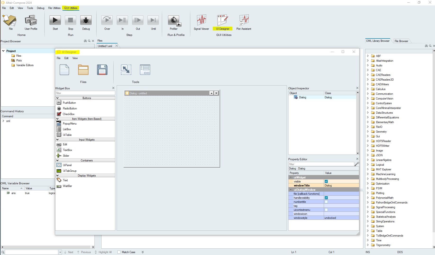
The UI Designer toolkit provides an easy drag-drop method to create graphical user interface designs without manual coding. The intuitive workflow lets you assemble a GUI design with predefined objects, preview and modify the design, then save the design as an OML code skeleton that you can further develop.
UI Designer Documentation Page: https://help.altair.com/twinactivate/help/en_us/topics/compose/uidesigner_gui_create_t.htm
Note: It is always advisable to create the UI first before writing the bulk of the code
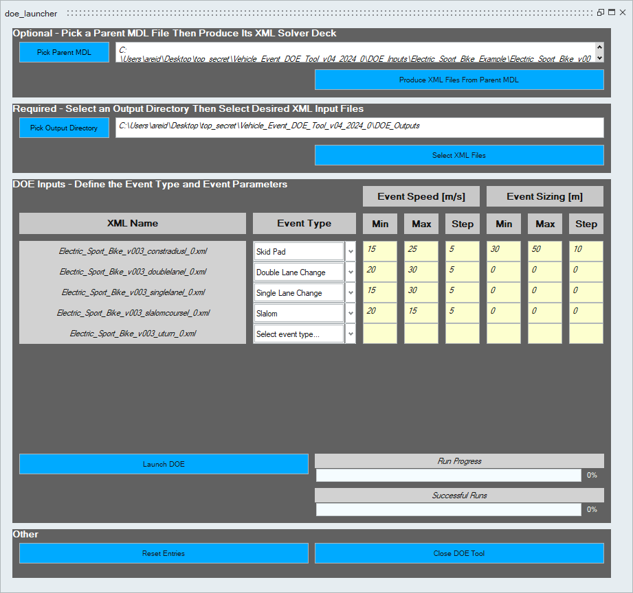
The final UI is displayed below, after considering all requirements for this project:

Compose Script Details
The automatically generated code from the UI Designer was used as the starting point for this project. It was eventually segmented into a main script, “vehicle_event_doe_gui_2024_0.oml”, and several “Helper Functions”.
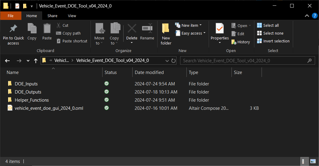
The main script and helper function details can be found summarized below:
- vehicle_event_doe_gui_2024_0.oml
- Main script
- GUI is launched by running this script
- aa_compileHelperFunctions.oml
- Used to load available functions from every script within the Helper_Functions directory
- Callback Scripts
- Scripting for when buttons, text fields, progress bars, etc. are interacted with within the GUI
- Function Scripts
- Logic required for the actual execution of the DOE
Example Run
In the DOE_Inputs folder, an example model has been provided of the electric sport bike example model with several duty cycle events already created. Those events include the constant radius, slalom, single lane change, double lane change, and a U-Turn event using the road course template. We will use this MDL as the basis for the example study.
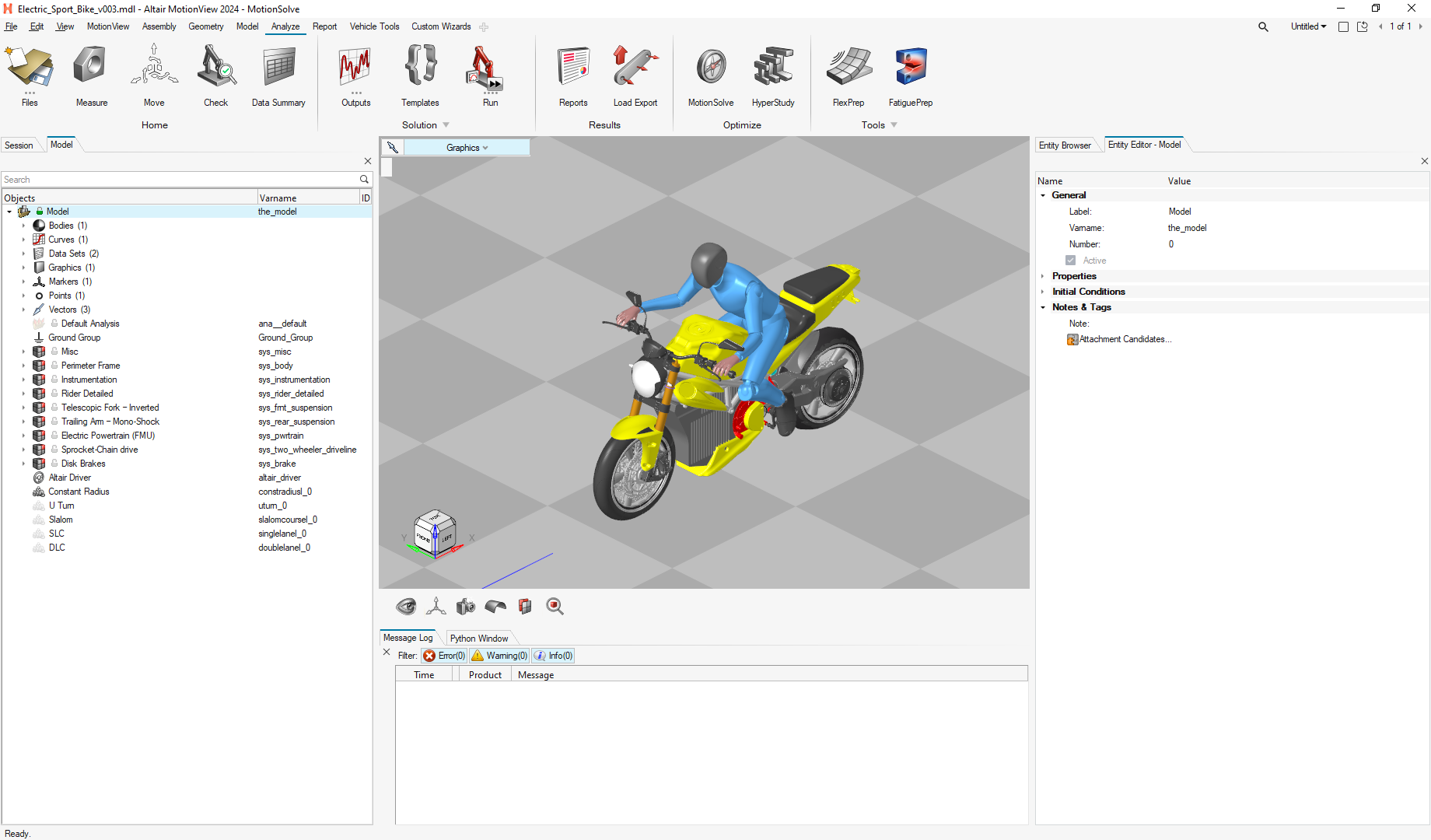
Run the main script, use the Pick Parent MDL button to locate the MDL in the DOE_Inputs folder, and then use the Produce XML Files From Parent MDL button to export the solver deck.
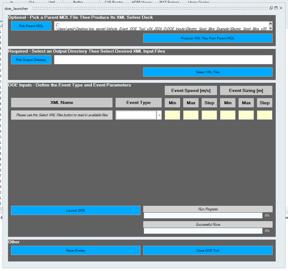
Use the Pick Output Directory button to choose where the run files for this DOE will write to then use the Select XML Files button to choose the desired XML input files. The selected files will then be dynamically displayed. The XML and ADF file pair will be scanned by the script to determine what type of event has been selected and display default values for the speeds and sizes. The event type can be manually changed if it was incorrectly read or if the script could not determine the event type, as shown with the U-Turn event below.
Not all events in this example have varying sizes, and thus their default values for Event Sizing will display as 0. If the User changes these values, no change may occur in the DOE as the required logic was only written for the constant radius (aka skid pad) event.
This DOE tool only works with simulations that require an Altair Driver File (ADF). When exporting a solver deck, the default analysis will also be exported (denoted by the “_ana__default” suffix). This XML file will not work as an input to this DOE.
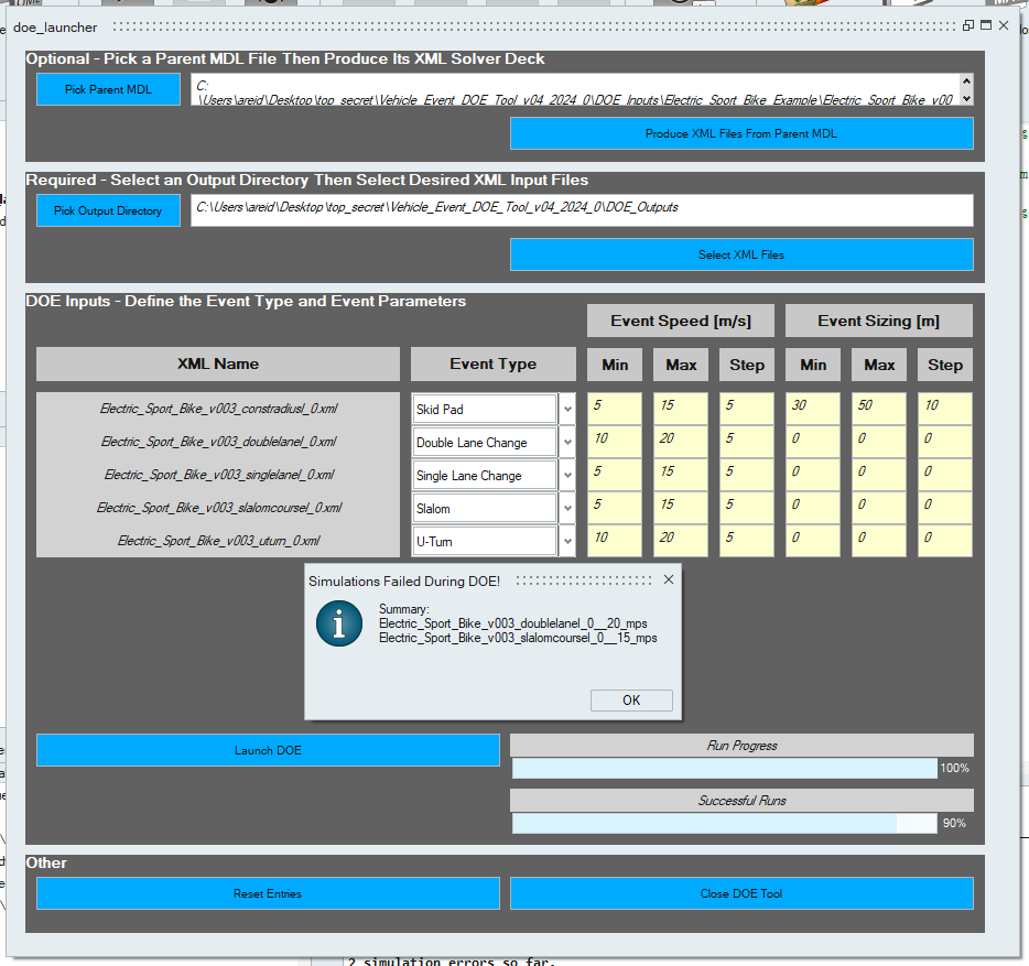
After launching this DOE, the User is provided with a message window which summarizes which runs have failed to complete. This is likely due to the vehicle falling over or the simulation locking up.
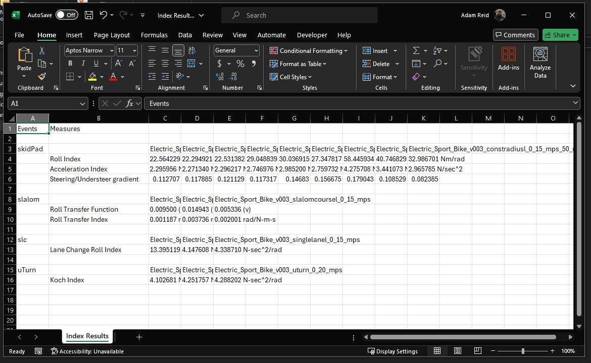
In the run folder, a directory will be created for each event and a summary CSV will be created as well:

In the event directories we will find the input XML, input ADF, and the Results folder.

In the Results folder we will find the simulation output files and the manually created plots for this event.

The Index Results CSV is a summary of the completed runs and any performance metrics requested for that type of event. These metrics were requested to be added by the Customer and can be modified as needed.
Hopefully this process can be of use to you in your Compose and MotionView journey!
Post-Requisite
Helpful Links
Looking for more material on MotionView/MotionSolve and Compose? Check out our available eLearning courses linked below!
Compose Introduction v2022