Spinning Motors: Interfacing an inverter drive circuit with any micro-controller to enable your e-Drives
Mayank Das
Embedded Software Engineer
Introduction
To enable your drive train, a key component of the model-based diagram is a DC/AC inverter. DC power supply being converted to three phase modulated voltages is achieved by such converter-based ICs, which also host current and voltage sensors. In our case, we use a BOOSTXL-3PhGaNInv.


BOSSTXL-3PhGaNInv EVM PCB top and bottom view
The BOOSTXL is header compatible with any TI C200 series micro-controller which a LAUNCHXL development board. We use a F28069M micro controller for the case of demonstration of the procedure of enabling eDrives diagrams.
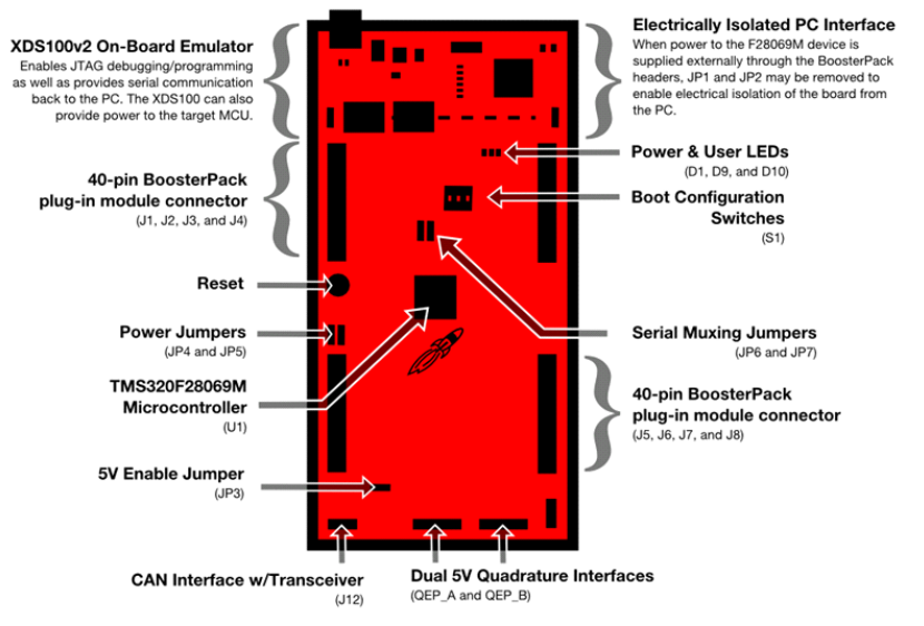
Overview of LAUNCHXL-F28069M Board
We will mount the inverter aligning J1 - J3 of both micro-controller and the inverter board.

Mounting BOOSTXL at forward LAUNCHXL position
eDrives
eDrives Add-on with Altair Embed is a library of tools and read-to-use examples, which enable electrical engineers and software engineers to spin motors and easily understand electrical drives with nuances.
Altair Embed provides a highly efficient environment covering all phases of developing control systems for electric drives in its eDrives add-on module. Its diagram-to-code capabilities frees electric drive engineers from manual coding and allows them to concentrate on developing the most optimal control system in the shortest time.

Features

- Library of examples with ready-to-use SIL, PIL, and HIL diagrams.
- Models for BLDC, PMSM, IM, IPM, Hall sensors, encoders, resolvers, and more. • Tools to build simulation diagrams for drive control.
- Drive enablement tools, examples, and tutorials.
- Seamless transition to any microcontroller, motor technology, or inverter. • InstaSPIN™ support for motor identification and efficient sensorless field-oriented control even at sub 1Hz rates.
- 16-and 32-bit digital motor control blocks, including PID, 3-phase PWM drivers, space vector waveform generators, Park and Clarke transforms, volts-to-hertz profiles, sensorless flux and rotor speed estimation, and quadrature-encoder-based speed calculator.
- Comprehensive Creating Motor Firmware Guide.
- Includes Altair® Flux Tracker (AFT), a robust algorithm for sensorless rotor angle estimation. (Know more about AFT)

Configurations
To start with, we will use a ready to use diagram from the eDrives library for Open-Loop Current Control of a PMSM.
All the settings which are needed to be configured in a diagram can be broadly divided into three sections:
- Enabling Inverter
- PWM Channels
- ADC Configurations
To enable the inverter, we must set GPIO 50 and/or 51 to active low, or ground. We do this by giving negative logic of CONVon_ to these GPIO input blocks. CONVon_ is a binary variable which is controlled by a button to switch on/off of the converter (See attached diagrams). This can be found inside '100Hz' block in the compile diagram.

Enable the inverter attached at forward boost position
Next, we ensure that the correct PWM Channels are being set. Since our driver is installed at J1 - J3 headers, by looking at the datasheet of F28069M, we can confirm that PWM 1, PWM, 2 and PWM 3 are attached to J4 header of the inverter. To find ePWM blocks in the diagrams, navigate to Main Motor Controller -- > ADC-PWM --> PWM block.


Further, from the design schematic of 3PhGaNInv, we can confirm the sequence of voltages and currents which are being sensed on the inverter and sent over to micro-controller over ADC channels.

Matching the 7 ADC channels ADCRESULT0 to ADCRESULT6 with their respective allocation, we get the following settings to be ensured in ADC configurations. Go to menu bar item Embedded --> F280x -> ADC --> ADC Config...

Another part to configuring the ADC channels from your new inverter is adjusting your ADC full scale values. These are set in a dialog box which appears when you right click on the 'Converter Variables' block. The ADC full scale values are calculated from the the schematic diagram of the inverter.

Here ADC Full Scale Voltage(V) = 3.33*(R56+R59)/R59 = 81.5V.
Similarly, we calculate ADC Full Scale Current = 33A

References:
[1] BOOSTXL-3PhGaNInv Schematic (Rev. A)
[2] LAUNCHXL-F28069M Overview User's Guide SPRUI11B–January 2015–Revised March 2019
Author:

Mayank Das
Embedded Software Developer
Over the past two years, I have been working on projects involving electric drives and their control techniques. I enjoy working on software that is knitted with hardware like embedded systems, actuators, motors, processors, etc. Glad to share my knowledge in our solution for efficient real-time embedded control using Altair Embed.
Educational background: MTech in Instrumentation and Signal Processing, BTech in Electrical Engineering from Indian Institute of Technology Kharagpur.
