Contact between 2d and 3d
Hello,
I would like to perform a linear static analysis(stiffness) of a composite wishbone (2D Shell). The forkends and brackets are Aluminium (3D-Solid). The solid elements are glued to the 2d element. For the glue, i made a solid component and imported the assebmly from CATIA (Material information of the glue is available). 1.How can I create the contacts between the parts? 2.Is there a special case between 2d and 3d elements to create a contact 3.Is 'TIE' the right contact method? I have got another question regarding diffrent subject: 4. Is there any possibility to change the coordinate system of my assembly in Hypermesh (optistruct)? Thanks in advance, best regards
Answers
-
Altair Forum User said:
Hello,
I would like to perform a linear static analysis(stiffness) of a composite wishbone (2D Shell). The forkends and brackets are Aluminium (3D-Solid). The solid elements are glued to the 2d element. For the glue, i made a solid component and imported the assebmly from CATIA (Material information of the glue is available). 1.How can I create the contacts between the parts? 2.Is there a special case between 2d and 3d elements to create a contact 3.Is 'TIE' the right contact method? I have got another question regarding diffrent subject: 4. Is there any possibility to change the coordinate system of my assembly in Hypermesh (optistruct)? Thanks in advance, best regards
hey
look at this tutorial : https://connect.altair.com/CP/SA/hwhelp/2019.1/os/topics/solvers/os/node_to_surface_vs_surface_to_surface_contact_r-1.htm#node_to_surface_vs_surface_to_surface_contact_r
cheers
0 -
Hi Farouk, I unfortunately didn't understand it so well. Can you please explain it to me?
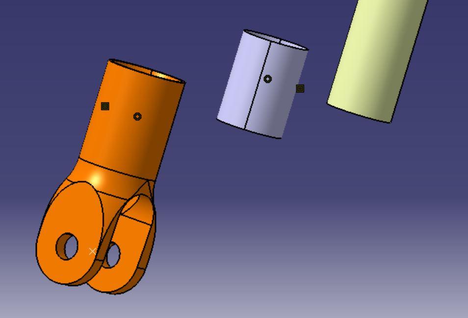
As you can see from the picture above, I have 3 parts and I want to make a glue contact between the parts. For the glue, I made a solid component to define the material information (the gray part is the glue).
(except the yellow part, the other two are solid)
How should I mesh the parts? Does my mesh have to be identical on top of each other? (2d, 3d)
Can I only mesh the contact surfaces identically (quad / hexa) and mesh, the rest of the solid part(where no contact arises) Tetra?
I need some help/tips to finish my thesis. Thank you in advance!
Best regards
0 -
Altair Forum User said:
As you can see from the picture above, I have 3 parts and I want to make a glue contact between the parts. For the glue, I made a solid component to define the material information (the gray part is the glue).
Hi mate !
You can use for example TIE constrain to link the master surface with the slave one.
Altair Forum User said:How should I mesh the parts? Does my mesh have to be identical on top of each other? (2d, 3d)
Normally, in contact problem we refine the mesh of the slave surface. But I think in your case, linear static analysis, there will be not so much difference. You can use the automatic mesher and mesh the parts using Tetra approximation.
Altair Forum User said:Can I only mesh the contact surfaces identically (quad / hexa) and mesh, the rest of the solid part(where no contact arises) Tetra?
It's okay if you use Tetra finite element ... But in Nonlinear static analysis, we recommend to refine contact interfaces (slave surface) with S2S discretization to ensure the convergence of the contact pressure.
Altair Forum User said:Thank you in advance!
You welcome mate /emoticons/default_smile.png' srcset='/emoticons/smile@2x.png 2x' title=':)' width='20' />
0 -
Hi Farouk,
I have some other questions. I would be very happy for your help!
1. I want to establish a SPC to another direction as the normal coordinate system allows me. I thought that I can create new axis direction and use it like in loads but it is not possible to choose it afterwards. Can you explain me the way to do this?
2. I´m testing the differences between S2S and N2S to be sure which one would be better for my analysis but I didnt really understand which one is better. Do you know how I can decide? (I used a plate (2D with 1 Ply) and a 3D-Solid cylinder, you find it attached)
3. So my last question is the difference between RBE2 and RBE3; on the picture I sent you above, there is a orange part with an 'x' on it. I want to define a load on this point. What would be your suggestion? RBE2 or RBE3? It would be really great, if you can explain it to me.
Thank you very much!
Best regards
0 -
Altair Forum User said:
Hi mate !
You can use for example TIE constrain to link the master surface with the slave one.
Normally, in contact problem we refine the mesh of the slave surface. But I think in your case, linear static analysis, there will be not so much difference. You can use the automatic mesher and mesh the parts using Tetra approximation.
It's okay if you use Tetra finite element ... But in Nonlinear static analysis, we recommend to refine contact interfaces (slave surface) with S2S discretization to ensure the convergence of the contact pressure.
You welcome mate /emoticons/default_smile.png' srcset='/emoticons/smile@2x.png 2x' title=':)' width='20' />
Hi Farouk, did you see my new message?0 -
Altair Forum User said:
Hi Farouk,
I have some other questions. I would be very happy for your help!
2. I´m testing the differences between S2S and N2S to be sure which one would be better for my analysis but I didnt really understand which one is better. Do you know how I can decide? (I used a plate (2D with 1 Ply) and a 3D-Solid cylinder, you find it attached)
Thank you very much!
Best regards
<?xml version="1.0" encoding="UTF-8"?>
Hi,
I'm gonna start with the second question. The difference between S2S, N2S or N2N discretization is : S2S allows to create a lot of contact element, so with it we will obtain a normal contact pressure more uniform and smooth that the others discretization.
I can send you an academic contact model if you want the see the difference between S2S and N2S.
Best regards,
0 -
Altair Forum User said:
Hi Farouk,
I have some other questions. I would be very happy for your help!
3. So my last question is the difference between RBE2 and RBE3;RBE2 allow you to define a rigid body whose independent dofs are specified on the first node (which is single = only one node) and the dependent dofs are specified on the second one (they can be more than one node ...) .
RBE3 allows you to define the motion of one node (we call it referent point) by an average (weighted average) of the motions of a set of nodes.
0 -
Thank you mate, what can you say about my first question?
' 1. I want to establish a SPC to another direction as the global coordinate system allows me. I thought that I can create new axis direction/local coordinate system and use it like in loads but it is not possible to choose it afterwards. Can you explain me the way to do this? '.
Thank you very much,
best regards0 -
Altair Forum User said:
Thank you mate, what can you say about my first question?
' 1. I want to establish a SPC to another direction as the global coordinate system allows me. I thought that I can create new axis direction/local coordinate system and use it like in loads but it is not possible to choose it afterwards. Can you explain me the way to do this? '.
Thank you very much,
best regardsSorry mate, I forgot it ! If I understand, do you want to apply an SPC following a 'relative' direction ?
0 -
Altair Forum User said:
Sorry mate, I forgot it ! If I understand, do you want to apply an SPC following a 'relative' direction ?
No problem mate, I did create a local coordinate system and I want to apply an SPC and lock a DOF in z-direction like in the picture.0 -
Altair Forum User said:
Yeah you can do it using this option : and <?xml version="1.0" encoding="UTF-8"?>
0 -
Altair Forum User said:
I already tried it Farouk but I got a failure that 'nodes defining a system cannot be assigned to it.', when I want to establish a set reference. Set displacement works, but I think that the assigning is not successful because after that I tried to define a force in z-direction on the global coordinate system. The force did not show in the local/self created coordinate system, but in the direction of the global coordinate system.
In my understanding when the assignment of the local coordinate system is finished, it should use the local coordinate as global coordinate. But maybe it has to do with the failure I get when I set 'reference'. And i cannot proof if SPC defined in the new coordinate system, because it doesnt show.
(To be sure: I chose all nodes of the component, where I defined a SPC, and as system the local coordinate system that I created, was used. )0 -
Altair Forum User said:
In my understanding when the assignment of the local coordinate system is finished, it should use the local coordinate as global coordinate.
Did you assign all the nodes of the model to the local coord. or only the NSET where you want to apply an SPC or Force ?
0 -
Altair Forum User said:
Did you assign all the nodes of the model to the local coord. or only the NSET where you want to apply an SPC or Force ?
As you can see in the last picture, the nodes were selected only from the part, where the SPC is defined (so not all nodes from the assembly) but I also tried to select all of the nodes from the assembly and some other combinations but it doesn't work somehow
0 -
Altair Forum User said:
As you can see in the last picture, the nodes were selected only from the part, where the SPC is defined (so not all nodes from the assembly) but I also tried to select all of the nodes from the assembly and some other combinations but it doesn't work somehow
I tried to run a simulation yesterday. All the nodes of the model are in the global coord. and I applied a load on a NSET in local coord and it worked ...
Is that what you want to do ? please correct me /emoticons/default_smile.png' srcset='/emoticons/smile@2x.png 2x' title=':)' width='20' />
0