Defining fan component inside a volume

Hi all,
I am trying to define a internal fan inside a domain. The problem is that I can´t find the correct way to define the fan.
Previously I had checked the tutorial. In the tutorial (ACU-T: 5100 Modeling of a Fan Component: Axial Fan)
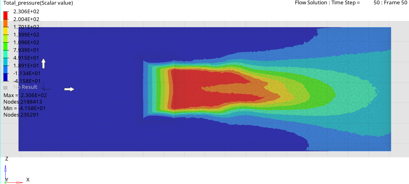
the fluid of the fan and the surface of fan component are inside a pipe and occupy the whole section (see next figure). where the brown section is the fluid of the fan.
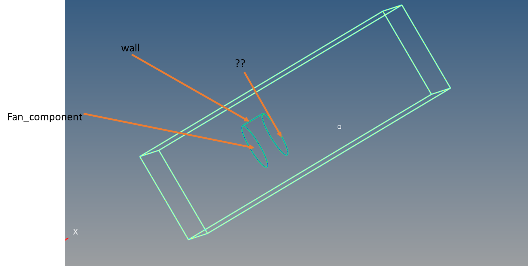
In my case, I have a small fan inside a fluid domain, see figure below:
The steps I´ve taken to prepare the model are the followings:
1. I create the 2d mesh of the cylinder surface and the outer domain surface.
2. I create the domain volumen elements taking into account the surface elements of the cylinder and the outer box.
3. I create the volume elements inside the cylinder.
The mesh is shown in the next picture:
The problem rises when I define the boundary conditions on the cylinder, see picture below.
1. In the fan inlet (left face of the cylinder), I define the fan component boundary condition
2. In the lateral walls I define the wall boundary condition,
3. But I don´t know what boundary condition I should implement on the right face of the cylinder. In the tutorial there is no boundary condition in the fan outlet, but in my case, if I delete the 2d elements of the cylinder in that part, there will be free edges there.
Is my understanding of the fan component correct?
I am creating the mesh and defining the setup in Hypermesh.
Best Answer
-
The 'outlet' of the fan volume should not have any Boundary Condition applied to it. Can you deactivate the boundary condition application in HM? I would recommend you apply a Surface Output to get the integrations on that surface. Then you can compare the resultant pressure rise and flow rates to what you expect.
The other option would be to leave the boundary condition type = wall active, then comment/remove it from the input file once exported. But you'll still want the Surface Output command.
1
Answers
-
The 'outlet' of the fan volume should not have any Boundary Condition applied to it. Can you deactivate the boundary condition application in HM? I would recommend you apply a Surface Output to get the integrations on that surface. Then you can compare the resultant pressure rise and flow rates to what you expect.
The other option would be to leave the boundary condition type = wall active, then comment/remove it from the input file once exported. But you'll still want the Surface Output command.
1 -
acupro_21778 said:
The 'outlet' of the fan volume should not have any Boundary Condition applied to it. Can you deactivate the boundary condition application in HM? I would recommend you apply a Surface Output to get the integrations on that surface. Then you can compare the resultant pressure rise and flow rates to what you expect.
The other option would be to leave the boundary condition type = wall active, then comment/remove it from the input file once exported. But you'll still want the Surface Output command.
Hi acupro,
I followed your advice although I put auto_wall boundary condition instead of deleting the boundary condition section from the input file, because I found out that in the tutorial´s inp file the fan outlet is defined in that way.
I built a case and ran it. However I find the results a little bit strange.
Here is the pressure contour:
The x velocity contour is in the next figure:
I am satisfied with the results of the x velocity. Here the axial alpha coefficient is 1 and the rest of the coefficients are zero. is the pressure distribution coherent? I mean it makes sense that before the fan there is a zone of low pressure as the fan is suckining air in but when I compute the pressure difference in the faces things don´t add up as you will see later.
Also I tried to add a tangential component by changing the tangential alpha coefficient to 1:
The pressure distribution is more strange, how could the pressure be the lowest at the exit of the fan?
On the other hand, I plotted the pressure increase in the fan fluid,
I think it is much lower than the value I expected, as the fan has the following caracteristics:
calculating by hand, I think the dP must be around
1/2*alpha*rho*u_tip^2 = 1/2*1.225*15^2 = 137.7 Pa
So there must be some error in the pressure distribution?
The residuals are shown in the next pitcure:
Any comment will be welcome, thanks.
0 -
Sebastian Yang said:
Hi acupro,
I followed your advice although I put auto_wall boundary condition instead of deleting the boundary condition section from the input file, because I found out that in the tutorial´s inp file the fan outlet is defined in that way.
I built a case and ran it. However I find the results a little bit strange.
Here is the pressure contour:
The x velocity contour is in the next figure:
I am satisfied with the results of the x velocity. Here the axial alpha coefficient is 1 and the rest of the coefficients are zero. is the pressure distribution coherent? I mean it makes sense that before the fan there is a zone of low pressure as the fan is suckining air in but when I compute the pressure difference in the faces things don´t add up as you will see later.
Also I tried to add a tangential component by changing the tangential alpha coefficient to 1:
The pressure distribution is more strange, how could the pressure be the lowest at the exit of the fan?
On the other hand, I plotted the pressure increase in the fan fluid,
I think it is much lower than the value I expected, as the fan has the following caracteristics:
calculating by hand, I think the dP must be around
1/2*alpha*rho*u_tip^2 = 1/2*1.225*15^2 = 137.7 Pa
So there must be some error in the pressure distribution?
The residuals are shown in the next pitcure:
Any comment will be welcome, thanks.
Can you also confirm the volume/element set for the fan is 0.05 in the flow direction? (This is the 'fan thickness' parameter. Can you also measure to make sure the distances are as you expect?
Do you have the experimental fan-curve for the fan? It's easiest to use Method > P-Q Curve in HyperWorks CFD.
0 -
acupro_21778 said:
Can you also confirm the volume/element set for the fan is 0.05 in the flow direction? (This is the 'fan thickness' parameter. Can you also measure to make sure the distances are as you expect?
Do you have the experimental fan-curve for the fan? It's easiest to use Method > P-Q Curve in HyperWorks CFD.
Hi acupro, yes I made sure that the fan thickness and the volume set´s length match.
I do have the experimental curve. Here I used a constant coefficient to test if the definition of the fan is correct. Lately I will use the curve to try to validate it, but I think it has been modelled satisfactorily as when I check the total pressure rise in the fan, see the next two figures.
axial alpha coef = 1
axial and tangential alpha coeff =1.
I need to test the curve but overall I guess it has worked, the pressure decrease we had seen before might be because the velocity of the flow increased a lot.
0