Initial Displacement in Flask
For shake of knowledge i tried to feed initial displacement for 10ms as imposed dis placement (T= 0, 0 Disp= 0,10). As below in given image.
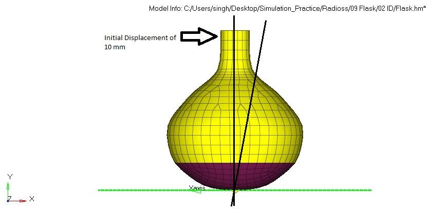
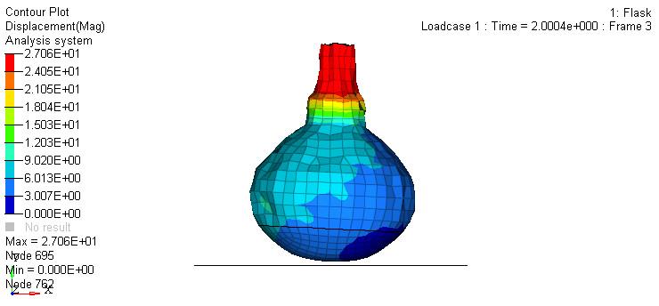
What i expect - flask should oscillate about center axis. But in results what i found there is huge vibration in flask as shown in figure
Later on i tried with initial velocity (1cm/sec) also. but same happened.
Can anyone explained why it happened ?
here my unit assumption in (mm,kg,ms). Related .rad file and .h3d files are attached.
Answers
-
Some modifications have been done. Check whether this helps you.
1. The lower thickness value may cause it to vibrate due to the imposed displacement. So it has been increased
2. A negative value is provided in the gravity curve to denote that the gravity is acting in the - Y axis
3. constrains were provided to the base to restrict the movement in other direction expect in X
0 -
Thanks Pranav Hari for reply,
1. I took steel material, even if thickness lesser than the given value it should not be vibrate likewise (We can think of our kitchen utensil made of steel, thickness in 1 or 2 mm and give some initial displacement..)
However, I also tried with initial velocity 1cm/sec but same happened (for such low initial velocity, there should not such vibration).
2. Yes, my flask should not move in space, so I provide gravity load.
3. CAE should simulate actual behaviour, I don't think any constraint needed after defining gravity load and initial displacement.
The model u sent here having thickness of 10 & 12 mm (we cant even think about such thick flask made of steel). its weight 5.3 kg (In actual weight of flask should be around 0.5 kg)...still having huge vibration and improper displacement on flask neck.
Plz provide better solution.
0 -
In your model, you have given a thickness of 0.1 mm. Can you please confirm this whether its 1mm or 0.1 mm.
0 -
Hello pranav,
I gone through many iterations by changing parameters.
So by fault it was 0.1 mm.
Its actually 1 mm for top and to increase weight at bottom some more thickness to bottom (2mm or 2.5 mm).
Sorry for that.
0 -
Thanks for the update. I will try and update you with a better solution.
0 -
Very thanks.
0 -
Hi @GAJENDRA KUMAR NHAICHANIYA
the trouble is caused by DT/NODA/CST card (I cannot explain why, but it causes excessive hourglass). The model runs fine if this card is turned off or QBAT or QEPH shell property element formulations is used (Ishell=12 or 24).
To get oscillations about a single node at the bottom you should constrain it in all translational DOF.
0 -
Hi Hyperman
Thanks for great observation, i also observe the same after you told.. as in below figure.
I really appreciate your comment. There is no option for super like otherwise i super liked your comment.
I want to know how you approached to solve issue ?
Altair Forum User said:(I cannot explain why, but it causes excessive hourglass)
now its mystery for me too /emoticons/default_biggrin.png' srcset='/emoticons/biggrin@2x.png 2x' title=':D' width='20' />
0 -
Glad to help. I see you too are willing and able to help for the benefit of Hyper-community. /emoticons/default_wink.png' srcset='/emoticons/wink@2x.png 2x' title=';)' width='20' />
Usually, for debugging models I start with Tools>modelchecker and continue with the process of elimination (turning off cards that are either unnecessary or adding complexity).
In this case, plotting energies could be a clue to hourglass issue, which could also be observed in animation.
In your energy plot, the total and internal energies are negative- you probably scaled the y component by -1
This is the energy plot for the edited model, where hourglass energy is 0 throughout due to QEPH formulation:
0 -
This help a lot.
Thanks.
I want to discuss further on same.
As we found higher hourglass energy cause of such behavior. But in Hourglass theory i found - such higher hourglass energy (excessive deformation) found when reduced integration element are subject to bending load.
1. we don't have such high bending load.
2. However, i tried to simulate with increased integration point (N - Number of integration points through the thickness).
Of course hourglass energy reduced compare to previous simulation but still it was more than the total energy of system.
3. Where i can get more detail of QEPH shells formulation (Ishell=12 or 24)
0 -
1. There is a bending load near the top and hourglass can propagate through coarse mesh
2. For material /MAT/LAW1 (ELAST), an only membrane behavior happens if N= 1. Otherwise, N is ignored and global integration is used.
3. Please refer to Free eBook: Crash Analysis With RADIOSS – A Study Guide for details
Also check tutorial RD-E: 0100 Twisted Beam Example
0 -
very much thanks again.
Its big data i'll take time to read and may discuss again if any doubt.
0