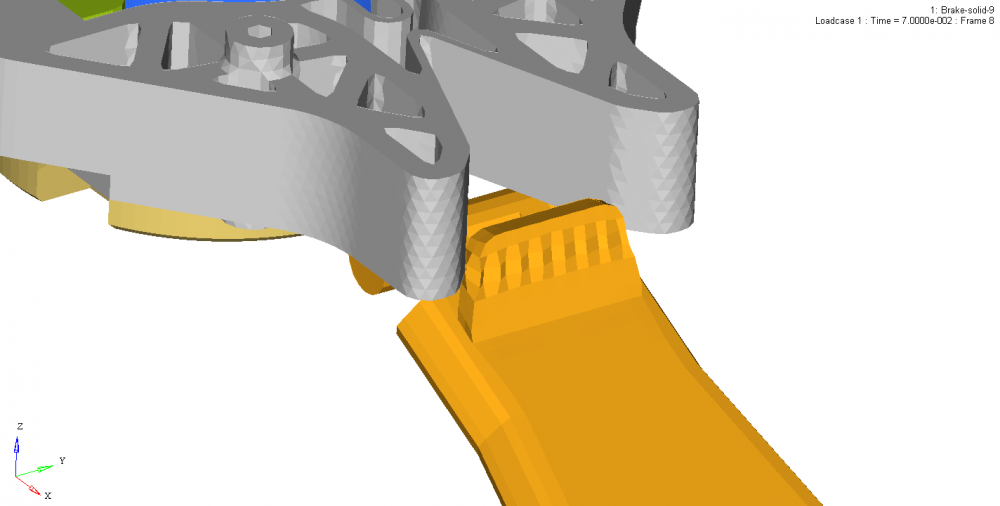
Element distortion @ contact interface
Hi,
I am trying a brake problem in Radioss.
Both type7 and 11 interface are used with Istf=4, Igap=2, Intatct=6, Iform=2 , No intersections/ penetration in the model and out file.
Please have a look at the animation and out file, let me know whats might be the reason for element distortion.
Answers
-
Hi Karthic,
You can try slightly increasing the Gapmin value.
Also recheck the material parameters. If issue persist please share the model file.
0 -
Hi George,
I tried increasing the Gapmin value.
Rechecked the material and tried running with steel material too
Please find the model in drop box and guide me to solve the issue.
Thank you.
0 -
HI Karthic,
Please try these workarounds:
Instead of making all the components same material try making the 'lever' component a more stiffer one and others less stiffer.
Also introduce a self interface for the lever component.
0 -
Hi George,
I tried running with lever as steel and other part a plastic. But still the same issue of Element distortion @ contact interface persist.
Please help me in resolving this issue and let me know the reason for Element distortion.
Thank you
0 -
-
Great George, Thank you for the valuable support
0 -
Hi Karthic,
Check the Interface 1 in the model as it is controlling the time step of the run. Check the interface for any penetrations also.
0 -
Hi George,
Yes, the NODES WITH HIGHEST MASS CHANGE belongs to the component of the interface.
NODE MASS MASS0 DM/MASS0
105520 0.9956E+18 0.2877E-09 0.3461E+28
104978 0.9956E+18 0.3502E-03 0.2843E+22But there are no penetrations in the interface. Also i have used the Type7 contact parameters as shown in image.
0 -
Hi Karthic,
I ran your model file with only change in solid formulation and it ran without any issues. The same video has been sent your mail.
Which HyperWorks version you are using, please try in the latest.
0 -
Hi George,
The file you ran is not the complete model. Sorry that i have not give you the entire model.
The errors which i mentioned is coming in the full model.
I have shared the new model to your FT link.
Thank you for the valuable support
0 -
Hi George,
We have 2017.2.2 updated, I am sorry that i didn't update you regarding the full model.
0 -
Hi Karthic,
Check the material for shoe and ensure the parameters are correct.
For Inter 1 put a small Gapmin value and check for penetrations. Also put Stmin=1000 and try running.
It seems like the shoe component is moving inside the spring component, that is a 'play' is there for shoe component. You can try with Type 2 interface between them instead of Type 7.
0 -
Hi George,
I will try all the above suggested and get back to you.
Thank you.
0 -
Hi George,
There is no issue with the brake material, we have already used the same material in the old files and trials which are working fine.
0 -
Hi George,
Altair Forum User said:Hi Karthic,
Check the material for shoe and ensure the parameters are correct.
For Inter 1 put a small Gapmin value and check for penetrations. Also put Stmin=1000 and try running.
It seems like the shoe component is moving inside the spring component, that is a 'play' is there for shoe component. You can try with Type 2 interface between them instead of Type 7.
All the above points mentioned by you exists in the trial model in which you have changed solid formulation and it ran without any issues.
Then how your telling that these are issues in the new model ?
0 -
Hi Karthic,
Since the run time was more for the trial model we didn't run it for the whole time, and moreover we were only checking the element distortion happening during simulation. And only when the run advances we can check for other issues and can suggest the changes/workarounds.
Moreover in the trial model you have given, only the material law used was /MAT/LAW2 (elasto-plastic material) for the entire model, but for the full model Law69 (hyperelastic material) is introduced and also for shoe component material values are different from the last model. And so it was recommended to check these material values.
0 -
Thank you George , I am trying the suggested checks and changes. will get back to you with the updates.
Have a great day
0 -
Hi George,
How Gmin value is influencing the interface time step?
0 -
Hi Karthic,
Penetrations result if a slave node is closer to the master segment than the calculated gap. Since the interface stiffness is nonlinear, the slave node cannot cross the master segment. If there is large penetration, the interface stiffness becomes large, leading to reduced time step.
Specify minimum thickness of the model to avoid numerical issues for Gapmin.
0 -
-
Hi Karthic,
The above approach seems correct.
Create an output block for contact and from the T01 file you can plot the normal resultant force for the contact (NF).
Also you can generate animation files containing vectorial data for contact force using /ANIM/VECT/CONT
0 -
Hi George,
what are |FN|, absolute value of normal Force?
In my results the absolute values are too high than the resultant normal force.
0 -
Hi Karthic,
|FNX| is the absolute value of normal force of the X-component of the contact force. It is the X-component of normal contact force applied to the master segment due to slave node.
Please go through the Help menu on /TH/INTER where this is shown.
Normally we check for the normal forces and resultant force.
0