Dear Moderator,
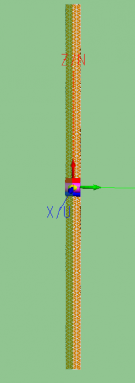
Consider a half-wavelength strip dipole placed in the origin and oriented along the z-axis with the width along the y-axis.
Case 1: Dipole is excited at the (edge-)port with 2V. SWE coefficients up to order n = 10 are requested and exported in an .sph file.
Case 2: The structure is removed and the .sph file from case 1 is used as a source and placed in the origin. The equivalent 'virtual' dipole source has the same orientation as the meshed dipole with a voltage source from case 1.
Therefore, two problems are equivalent.
For a half-wave dipole, FF boundary is set at 2D^2/lambda = 0.5*lambda.
Consider the field request in a single point with different radii: (r, theta, phi) = (r, 90, 90)
Note that I am always requesting the Near Fields (for radii in both the near-field and the far-field).
For FF radii down to approximately 0.7*lambda, both ways yield the same results. For radii between 0.5*lambda and 0.7*lambda, fields obtained in these two ways start to diverge.
A numerical example:
- > Voltage source: E (0.5*lambda, 90, 90) = - 87.6389 - 86.2589 j.
- > SWE source: E (0.5*lambda, 90, 90) = - 87.2327 - 90.8919 j.
The difference is large, around 3 in magnitude and 2 degrees in phase.
To obtain this value from a set of SWE coefficients, one needs to either expand the field at a particular spherical coordinate using spherical harmonics and Hankel functions, or calculate the far-field first and use the spherical propagation factor exp(-jkr)/r for back-propagation. The former is more accurate for smaller radii. However, even if FEKO used the latter, radii between 0.5*lambda to 0.7*lambda are still in the antenna far-field. Therefore, the calculated fields should be more correct compared to the full-wave voltage source radiated pattern, which I hope we can take as a reference.
Furthermore, I compared the results to my own SWE code:
- > SWE2: E (0.5*lambda, 90, 90) = - 87.6630 - 86.3141 j, which is much closer to the full-wave result.
So my questions are:
1) Why do the results using voltage source and equivalent spherical modes source differ in the 'closer' far-field region?
2) How does FEKO calculate the back-propagation from the SWE source? If the answer is using the exp(-jkr)/r term, would it not be more natural to expand the fields using spherical harmonics and Hankel functions (since you already have the coefficients)? If FEKO does use the harmonic expansion, why does it give the incorrect value for the radii at the FF boundary.
The question is important for my research problem so I hope you will be able to answer.
Best regards,
Tomislav Marinovic (KU Leuven, Belgium)
<?xml version="1.0" encoding="UTF-8"?>