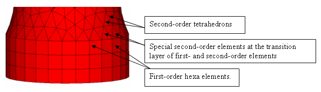
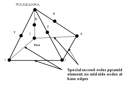
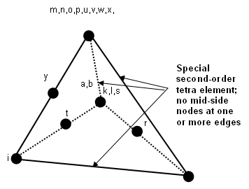
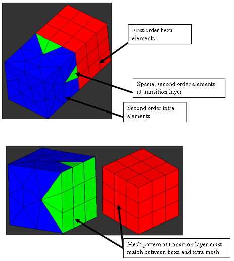
ANSYS Convert to Special 2nd Order Macro
When you run the Convert to Special 2nd Order macro, a mesh matching is used to remove the mid-side nodes at the shared edges between these first and second order elements.
These special elements will be imported as full second-order elements, including mid-side nodes.
Imported full second-order elements are exported as special elements, thereby restoring the original element configuration. Similarly, special second-order elements created in HyperMesh are also exported as special second-order elements.
- Mesh the part for first-order with hexa or penta elements. Place these elements in a collector with the correct element type (SOLID45).
- Mesh the mating volume with second-order tetra elements. Place this mesh in a separate component with the correct element type (SOLID95 or SOLID92).
- Ensure that the two mesh patterns have a common layer with shared edges between.
- From the ANSYS Tools page of the Utility menu, click the Convert to Special 2nd Order macro.
- Select the first-order component from the drop-down menu that shares a common face with the second-order meshed component.
- Select the second-order meshed component in the next drop-down menu and click Apply. The special order elements are generated
- Export the file. Read it in the solver and check the elements. The following images show examples of proper meshing for the above practice.Figure 4.