Hello,
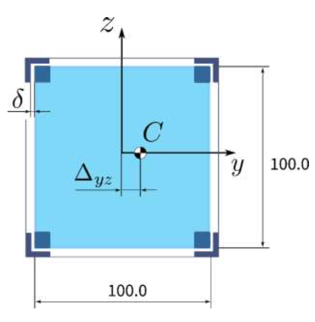
I have a problem regarding a clearance fit.
I already checked the eBook 'Practical Aspects of Finite Element Simulation' but could not find anything helpful.
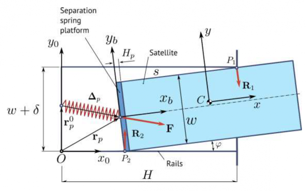
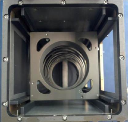
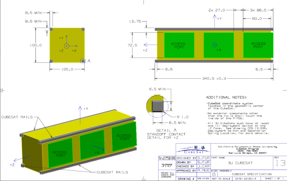
My thesis is about a structural analysis of a CubeSat satellite inside of a Deployer Case.
So I have the model of the satellite and the case. In space the Deployer Case will open up and a spring inside kicks out the satellite.
Former attempts to model the connection between both models failed because analysis results have been unrealistic.
I used RBE2 elements (all 6 dofs constrained) on both contact surfaces and connected them with a rigid CBUSH element. I just realised how wrong that is.
My new idea for a realistic clearance fit is to keep the RBE2 elements (6 dof constrained) at the case, replace the RBE2 elements on the satellite by RBE3 elements (only 1 dof constrained in normal direction) and connect them with a rigid (CBUSH).
Is my new idea also false?
Do you have any idea how to model a clearance fit between satellite and case according to the pictures attached?
<?xml version="1.0" encoding="UTF-8"?>
<?xml version="1.0" encoding="UTF-8"?>
<?xml version="1.0" encoding="UTF-8"?>.PNG.18f29ffa7d03d0bc15a1bfeae765e694.PNG)
<?xml version="1.0" encoding="UTF-8"?>
<?xml version="1.0" encoding="UTF-8"?>