roll bending

Altair Forum User
Altair Forum User
Altair Employee
edited October 2020 in Community Q&A

hi 

i am doing simulation on 3 point roll bending in radioss solver 

first step i applied displacement to the top roller in z direction then i applied peripheral velocity to 3 rolls then i stopped the velocity again applied top roller displacement  and given velocity of the roll in different direction.

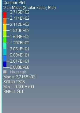
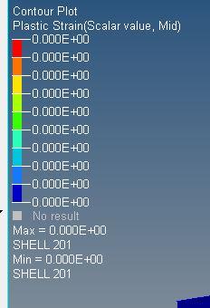
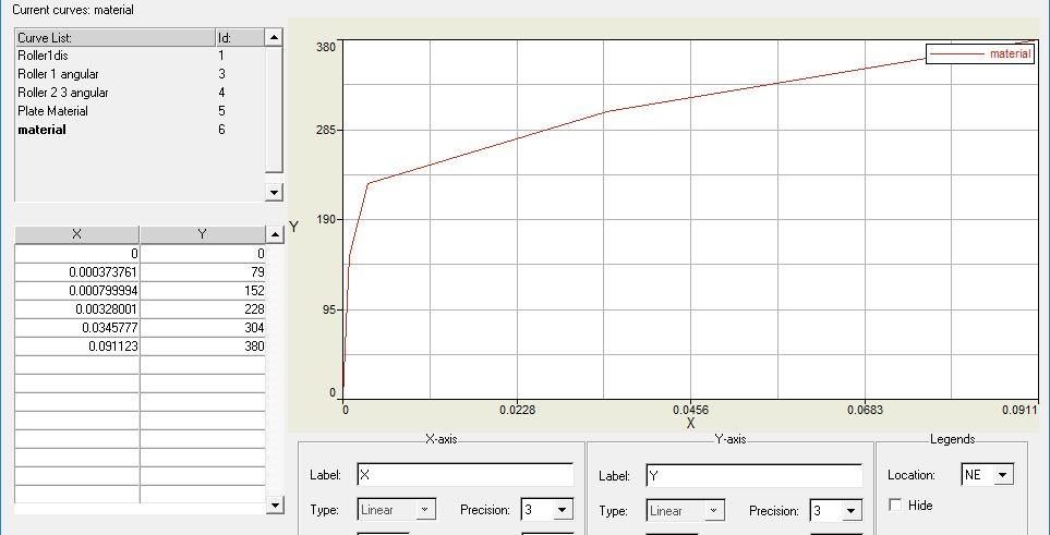
i am not getting the plastic strain value while the stress i am getting larger than then the yield value material.JPG.d11820e26574acf760d314ed7e691b0f.JPGstress.JPG.5c662edd926962782acfe7510f1760d0.JPGstrain.JPG.a8a826f63510a7de83ecd10c7bfc053d.JPG
Tagged:

Answers

  • Altair Forum User
    Altair Forum User
    Altair Employee
    edited January 2019

    i used the material M36PLAS_TAB 

  • Simon Križnik
    Simon Križnik Altair Community Member
    edited January 2019

    Hi,


    the issue is with the stress-strain curve: the first point of yield stress functions (plastic strain vs stress) should have a plastic strain value of zero at yield stress. In your case, the first s-s set should be 0 plastic strain at 152 stress (the second 0.002481 plastic strain at 228 stress and so on), while the linear elastic part is described by E parameter= 190000 (Young's modulus).

  • Altair Forum User
    Altair Forum User
    Altair Employee
    edited January 2019

    Hi ivan

    Thanks for your reply i have made the changes for the stress strain curve that 0 strain is at the yield point of the material and the curve progresses as mentioned below. even though i am not getting plastic strain value.  

    material.JPG.f4946d1fbde6543a0c73d0bce8f1a2d7.JPG<?xml version="1.0" encoding="UTF-8"?>stress.thumb.JPG.dba45577fd174689f0d25bf090f90efb.JPG<?xml version="1.0" encoding="UTF-8"?>strain.thumb.JPG.ab0344aa3ae42bd4abcd2c9fcfa40611.JPG

  • Simon Križnik
    Simon Križnik Altair Community Member
    edited January 2019

    You should subtract the elastic strain (0.000799994) to get only plastic strains. So the table should be:

    0 @ 152

    0.002481 @ 228

    and so on


    It is odd the plastic strain is not visible- can you share the model?


    Attached is an example of law 36 with plastic strain.

    Unable to find an attachment - read this blog

  • Altair Forum User
    Altair Forum User
    Altair Employee
    edited January 2019

    Hi ivan 

    Sorry for late reply 

    i attached file please check.

    Unable to find an attachment - read this blog

  • Simon Križnik
    Simon Križnik Altair Community Member
    edited January 2019

    The issue was with solid property parameter Isolid=12, which is an obsolete standard 8-node solid, full integration (no hourglass). Use Isolid =17 (H8C) or 24 (HEPH) instead.


    I have edited stress-strain curve and set up advanced mass scaling to speed up computation. 

    Unable to find an attachment - read this blog

  • Altair Forum User
    Altair Forum User
    Altair Employee
    edited January 2019

    thanks ivan 

    i am using older version v14 can u share me the .rad file please


  • Simon Križnik
    Simon Križnik Altair Community Member
    edited January 2019
  • Altair Forum User
    Altair Forum User
    Altair Employee
    edited January 2019

    thank you so much ivan

    in 3 roll bending simulation can we do the simulation in stage wise  (i.e) first step the top roller is moved down that boundary condition is specified for this stage and second stage rotation of rolls now boundary condition is differ from first stage  


    what is multi stage process in hyperform is that helpful for my case?????

    i need to consider the spring back also 

  • Simon Križnik
    Simon Križnik Altair Community Member
    edited January 2019

    It is possible to carry out simulation in stages. There are various possibilities:

    -most boundary conditions can be switched on/off through Tstart/Tstop parameter

    -contacts can also be switched on/off (Tstart/Tstop parameter)

    -rigid bodies can be activated or deactivated with a sensor or with the options /RBODY/ON and /RBODY/OFF in the Engine files

    -multiple engine files can be defined with different simulation controls


    I am not (yet) familiar multi-stage process in Hyperform so I can't comment on that. But given HF uses Radioss solver it should be possible to set up a similar simulation.

    Check Example 24 – Spring-back:

    http://altairuniversity.com/wp-content/uploads/2012/08/Example_25.pdf

  • Altair Forum User
    Altair Forum User
    Altair Employee
    edited January 2019

    hi ivan 

    can u explain me briefly about Tstart/Tstop parameter 


    i need to fully constrain the plate at the specific time i have created constrain for this as in the image is that an appropriate way. when i am running this i am getting the warning as a incompatible kinematic condition and it simulated is get stopped. 


    thanks 


    <?xml version="1.0" encoding="UTF-8"?>Capture.JPG

  • Simon Križnik
    Simon Križnik Altair Community Member
    edited January 2019

    Tstart/Tstop parameters on /BCS card are used for /INTER/TYPE21 mapping, so it will not switch on/off boundary condition.


    To release DOFs, you need to use BCSR/TRA, BCSR/ROT engine cards. Please go through following examples, where this functionality is used:

    RD-E: 4200 Rubber Ring: Crush and Slide

    RD-E: 5501 Fan Blade Rotation Initialization

  • Altair Forum User
    Altair Forum User
    Altair Employee
    edited January 2019

    hi ivan 


    is type 21 is for shell element in type21 unable to select the slave as brick element


    for arresting the dof's i try one method 

    i created an second engine file to arrest DOF's of the component at a specific time by adding these commands 

    /BCS/TRA/XYZ

    node numbers 


    simulation get terminated because of mass error 


    releasing the dof's is fine works well is there any similar way for arresting the dof's 


  • Altair Forum User
    Altair Forum User
    Altair Employee
    edited February 2019

    hi @Ivan


    i am simulating the manufacturing process 3 roll bending process in radioss, early i used 3D model now i am trying with a  2D model, since plate thickness 3 mm

    For that i extracted the midsurface of the plate and assign the thickness of the plate as 3mm. i used P1_shell ishell=24 N=5 thick=3 Istrain=1. 

    i assigned the material property to roll and plate, boundary condition, contact every thing as same. 

    shell is bending only in the region inside the rolls, region outside the roll is not bending i have marked in the image .

     does i have used any shell parameters wrongly.


    i having problem in imposed velocity also that the rotation of roller. the roller is not rotating in both the direction i have assigned negative sign(-) to change the direction of roller in curve editor. 


    i have attached my file pls check 


    thanks 

    Capture.JPG.7094c4cd6afe3e24ea9a128f04c41054.JPG 


    Unable to find an attachment - read this blog

  • Simon Križnik
    Simon Križnik Altair Community Member
    edited February 2019

    Hi,


    the region outside the roll is not bending because you had constrained the rotational DOFs of the plate. Only Y translations should be constrained so plate remains centered.

    The shell formulation is correct- I would add Ithick=1 so thickness change is taken into account.

    Note however the thickness (3mm) to length (10mm) ratio of plate elements is 0.3.

    Thick shells are used when thickness to length ratio is between solid and thin shell recommended range:


    0.jpg

    When h/L is large, shear deformation is at its maximum importance and the user should use solid elements. When h/L is small, transverse shear deformation is not important and thin shell elements are the most effective choice.


    The initial downward displacement of the top roller happens in 5ms. Such a rapid loading induces inertial effects, which might be unwanted if you are trying to simulate a quasistatic event. 


    The negative sign will reverse the rotation- check the model attached. If you have trouble visualizing rotation in HV, use Shaded elements and mesh lines view, hide just one element of roller, contour velocity or show undeformed shape in wireframe mode. Be careful when defining curves; when simulation goes outside the defined range it will extrapolate the slope- in your case the velocities would keep increasing after 155ms.


    Unable to find an attachment - read this blog

  • Altair Forum User
    Altair Forum User
    Altair Employee
    edited February 2019

    Hi @Ivan


    thank you, its clear......


    energy error% it is goes on increasing 


    CYCLE    TIME      TIME-STEP  ELEMENT          ERROR  I-ENERGY    K-ENERGY T  K-ENERGY R  EXT-WORK MAS.ERR
    2447500  2985.      0.1239E-02 NODE          27 -89.9%   230.2       9.932       5.925       2448.       0.000    
         ANIMATION FILE: 2D_SHELL_A5972 WRITTEN
    2448000  2986.      0.1239E-02 NODE          27 -90.0%   229.3       10.88       5.927       2449.       0.000    
         ANIMATION FILE: 2D_SHELL_A5973 WRITTEN
         ANIMATION FILE: 2D_SHELL_A5974 WRITTEN
    2448500  2987.      0.1239E-02 NODE          27 -90.0%   228.4       11.67       5.930       2450.       0.000    
         ANIMATION FILE: 2D_SHELL_A5975 WRITTEN
    2449000  2987.      0.1239E-02 NODE          27 -90.0%   227.7       12.38       5.935       2450.       0.000    
         ANIMATION FILE: 2D_SHELL_A5976 WRITTEN
    2449500  2988.      0.1239E-02 NODE          27 -90.0%   227.0       12.98       5.919       2451.       0.000    
         ANIMATION FILE: 2D_SHELL_A5977 WRITTEN


    i didn't specify any mass scaling /DT/NODA/CST or /DT/AMS

  • Simon Križnik
    Simon Križnik Altair Community Member
    edited February 2019

    Negative Energy Error represents energy dissipated from the system and this can be from many sources including plastic deformation and Hourglass energy. 

    If you have included coefficient of friction then the energy error is due to coefficient of friction which is justified. If this amount of energy error is there when no coefficient of friction is defined, then it may be a case of penetration which is problematic.

  • Altair Forum User
    Altair Forum User
    Altair Employee
    edited February 2019

    hi @Ivan


    simulation works fine but the plate (2D shell model) is vibrating much. i have applied load gradually. what might be the issue in the model . refer the

    video i have attached. 

    Capture.JPG.5a72b79b574c940f2ab6d370b840ee31.JPGCapture1.JPG.1348878679ab966a0910c0438c27de59.JPG 

    Unable to find an attachment - read this blog

  • Simon Križnik
    Simon Križnik Altair Community Member
    edited February 2019

    Hi,


    The vibrations are due to loading being applied using step (jagged) functions. If we differentiate the displacement and velocity functions we get high accelerations leading to large forces and vibrations. To avoid vibrations the functions should be smooth and/or Dynamic relaxation (/DYREL) or Rayleigh damping (/DAMP) could be used.

  • Altair Forum User
    Altair Forum User
    Altair Employee
    edited February 2019

    hi @ivan 


    thanks for your reply.

    In Rayleigh damping (/DAMP) how to find the values of alpha & beta. 


    And if i apply the values for alpha and beta means the time step which i imposed through Advance Mass Scaling (/AMS) is not taken into consideration.The simulation runs on with the actual time step... What is the reason behind this issue.


  • Simon Križnik
    Simon Križnik Altair Community Member
    edited February 2019

    The Rayleigh damping coefficients can be obtained experimentally or calculated (see attached) However, in practical applications they are estimated and adjusted based on engineering intuition. I got good results on some models using Beta=10 and leaving Alpha blank. Rayleigh damping will reduce the timestep so adjust timestep controls accordingly.


    http://ejge.com/2003/Ppr0318/Ppr0318.pdf

    https://www.researchgate.net/post/Any_suggestions_on_Rayleigh_damping_coefficients


    Unable to find an attachment - read this blog

  • Altair Forum User
    Altair Forum User
    Altair Employee
    edited February 2019

    hi @Ivan


    i will do some iteration on this Rayleigh damping coefficient and lets u know if i had any difficulties.....


    i having doubt in the spring back i used the implicit spring back option as mentioned in the example 25 but my results are not that much correlating .

    In implicit spring back what kind of solver should we use in tutorial it mentioned /IMPL/SOLVER/2 but in the file which is mentioned in the tutorial DBEND_44 they mentioned /IMPL/SOLVER/1 


    i have attached the tutorial and file from tutorial for reference.

    Capture.PNG.60d55ce43194c9f2098fdc2b59ff2296.PNG


    Unable to find an attachment - read this blog

  • Simon Križnik
    Simon Križnik Altair Community Member
    edited February 2019

    Hi,


    you should first smooth the loading functions and only then reduce any remaining vibrations with damping.


    I don't have enough experience with implicit spring back to be able to give useful advice.

  • Altair Forum User
    Altair Forum User
    Altair Employee
    edited February 2019

    hi,


    if we use the damping for controlling the vibration in the plate, does it affect the spring back???

  • Simon Križnik
    Simon Križnik Altair Community Member
    edited February 2019

    Springback results are sensitive to the magnitude of damping factor, especially when unphysically high damping is used.


    Check the following papers for details:

    https://www.sciencedirect.com/science/article/pii/S0924013604003577

    https://www.sciencedirect.com/science/article/pii/S1000936113001751

  • Altair Forum User
    Altair Forum User
    Altair Employee
    edited February 2019

    thanks your reply i will read those journals.


    i am having a doubt does MAT36 will used for the springback analysis??

  • Simon Križnik
    Simon Križnik Altair Community Member
    edited February 2019

    In Example 24 – Spring-back Anisotropic elastoplastic Hill material model /MAT/LAW43 is used.

  • Altair Forum User
    Altair Forum User
    Altair Employee
    edited February 2019

    Hi @Ivan


    i facing problem during running the job that my simulation remaining time is keep on increasing with error percentage. i attached the text file  for reference. does the model have any issue in the contact??


    i have attached my model file please check


    Unable to find an attachment - read this blog

  • Simon Križnik
    Simon Križnik Altair Community Member
    edited February 2019

    Hi,


    Looks like the contacts are causing the large negative energy error. But the root cause is the too high timestep imposed by AMS. First, run with DT/NODA mass scaling until you get reasonable negative energy (15%) and mass error (2%) throughout the simulation. Then set up the AMS run trying to hit the energy error % of DT/NODA run (as well as stress and displacements). Set the Iflag=2 and Nprint=1000 to output the number of iterations before the convergence of the conjugate gradient in the out file (less than 30 is good). There should be only a few cycles where INTER is controlling the timestep. 


    It is recommended to use Iform=2 with contact friction.