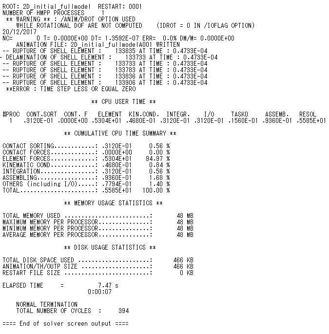
ERROR : TIME STEP LESS OR EQUAL ZERO in the case of Composite layup using RadiossBlock
Hello Friends,
I am trying to analyze three-point bending test of composite hat-stiffened structure with RADIOSS Block140 as a solver. MAT25 was used as material property of a laminar ply for the laminated shell element. And, PROP17 was used as laminated shell element for stacking multi plies defined by MAT25. Now I can visualize plies on the component. However, when I ran my task in RADIOSS, it gives me error list, which I am attaching with this question.So, could you help me to solve the following questions? Thank you!
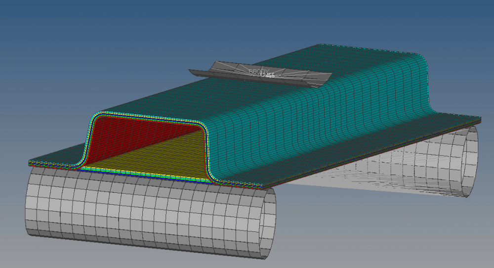
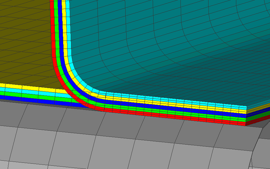
1)In the first two pics, the upper composite layup part has some penetration part with bottom part since it defaults that the midsurfaces are base surface in laminate, so how to change composite layup orientation in RadiossBlock, such as set midsurface as bottom.
2) The third pic shows:
** WARNING ** : /ANIM/DROT OPTION USED
WHILE ROTATIONAL DOF ARE NOT COMPUTED (IDROT = 0 IN /IOFLAG OPTION)
20/12/2017
NC= 0 T= 0.0000E+00 DT= 1.3592E-07 ERR= 0.0% DM/M= 0.0000E+00
ANIMATION FILE: 2D_initial_fullmodelA001 WRITTEN
-- RUPTURE OF SHELL ELEMENT : 133835 AT TIME : 0.4733E-04
- DELAMINATION OF SHELL ELEMENT : 133733 AT TIME : 0.4733E-04
-- RUPTURE OF SHELL ELEMENT : 133733 AT TIME : 0.4733E-04
-- RUPTURE OF SHELL ELEMENT : 133783 AT TIME : 0.4733E-04
-- RUPTURE OF SHELL ELEMENT : 133836 AT TIME : 0.4733E-04
-- RUPTURE OF SHELL ELEMENT : 133906 AT TIME : 0.4733E-04
**ERROR : TIME STEP LESS OR EQUAL ZERO
<?xml version="1.0" encoding="UTF-8"?>
Answers
-
Hi,
The out file shows that some elements are failing and thereby the time step is also dropping which finally results in the run termination.
Can you please share the model file so that we can review the model and can guide you.
0 -
Hi George,
Thanks for your reply.
Please check the attachment.
Thanks!
0 -
Hi,
When thickness is provided it will be assigned equally to the top and bottom directions of the midsurface.
Translate the midsurface components so that when when thickness is assigned it will not penetrate to the neighboring components. The panel component is 2mm thick. Translate the same 1mm in Z direction and similarly for the hat component also.And finally when interface is defined provide this gap as the Gapmin value for Type 7 interface.
As an example, when inetrface is defined between panel and support components provide the Gapmin as 1, so that at this value this interface will be activated.
I have a similar example file with me and the same is shared for your reference. You can follow the modelling concepts as in this file.
0 -
Hi George,
Thanks for your information.
After follow your suggestion, the above problem has been solved. However, new problems has occurred.
During the calculation, before contacting, it works well. However, when it began contacts, it shows 'WARNING INTERFACE 3 , NODE 457557 DE-ACTIVATED FROM INTERFACE'. I searched the forum, and found there is something wrong with contact definition (interface 7).
Could you help me figure it out? I don't know how to set up contact between hat part and panel part since they are welded together in the experiment.
I attached the .hm file and .out file FYI.
0 -
Hi,
Create a self interface (Type 7) for the hat component also. Check for penetrations also in the interface and remove or depenetrate those.
Also, between the hat and panel create a Type 2 contact.
Ensure the material parameters are correct.
0 -
Hi, George,
Thanks! I solved this problem by only setting up Type 2 contact between the hat and panel components. (I didn't create self interface (Type 7) for the hat component )
However, when I checked the contact force between the load and hat component, it showed zigzag trend show in pic. I am sure that the material properties are correct. How to solve this problem?
I attached the .hm, .h3d and T01 FYI. Thanks!
0 -
Hi Gregory,
The h3d and the energy plots looks fine for the model.
Please share the same deck files (_0000.rad, _0001.rad).
0 -
Hi George,
Thanks very much.
I attach the deck files FYI. Please check them.
0 -
Hi Gregory,
This is fine, and all other global parameters of the model are also fine. This could be because of the profile of the loading component.
And normally for resultant contact forces we get a similar curve,
0 -
Hi, George,
For the above 2D model, I have solved the problem. Thanks!
For using Mat 28, I created 3D model to investigate the fracture behavior of hat-shaped hollow beam subjected to static flexural loading, relevant tensile, compressive and shear nonlinear curves were created.
Although I have created /DT/BRICK/CST, the error information “time step less or equal zero” still occurred after several time step when the compressive stress reached to the compressive strength.
I searched the forum about the error, but cannot still solve the problem.
Please check the model attached here.
0 -
Hi Gregory,
In your model the elements are distorting badly leading to very low time step and it terminated the run. It seems to be from the material. You can check and confirm the material parameters.
Honeycomb material is an easily crushable one and for panel you can assign a separate material rather than honeycomb material. Also assign a self interface for panel and hat component.
0 -
Hi, George,
Thanks for reply.
According to your suggestions, some progress have been achieved, however, new problem also occurred.
In order to model delamination and save computation time, I created zero thickness 3D element as cohesive element between two layers of composite hollow beam according to
However, when submitted to calculate, too many warnings and error ID 760 happened as follows:
WARNING : ZERO OR NEGATIVE 3D SOLID VOLUME
DESCRIPTION :
ZERO OR NEGATIVE VOLUME 3D ELEMENT ID=2031 WITH VOID PROPERTY SETSo could you help me to figure it out? Thank you.
0