mass OPtimisation by changing square size and thickness

Altair Forum User
Altair Forum User
Altair Employee
edited November 2020 in Community Q&A

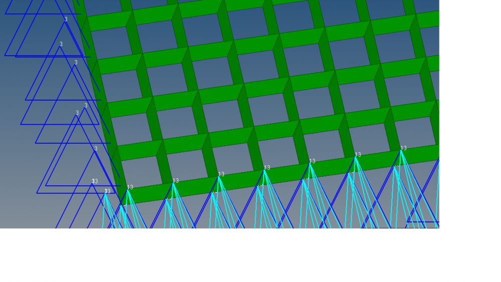
Attached is a Hypermesh deck of a structure whose mass I’m trying to minimize. The structure has a square shaped core covered on the top and bottom by composite facesheets. Shell elements have been used for modeling. The size of the square and the thickness of its wall determine the buckling characteristics of the facesheets. I’ve modeled using a square of side 6mm and its wall thickness is 1.5 mm (shown in the snapshot below). By varying the size of this square and changing the wall thickness, I’m looking to minimse the mass, the constraint being that the buckling factor must always be greater than 1.


Could you please help me achieve my objective?


Thanks,


Kushal Agarwal.


<?xml version="1.0" encoding="UTF-8"?>hm.png
Unable to find an attachment - read this blog

Answers

  • Altair Forum User
    Altair Forum User
    Altair Employee
    edited August 2017

    Hi @Kushgen


    Two approaches comes to mind:


    1) Do a shape optimization, this may change the shape of the square

    2) By changing the thickness of the shell elements you can change the size of the square. So you can do a size optimization.

  • Altair Forum User
    Altair Forum User
    Altair Employee
    edited August 2017

    Hello,


    1. the shape must be restricted to a square for manufacturing reasons, hence, size optimisation may not be relevant. A different shape is acceptable if the pattern is repetitive and manufacturable.

    2. the size of the square can't be changed independently else it'll not satisfy the buckling constraint.  the size must be changed in tandem with the wall thickness to respect the buckling constraint

  • Altair Forum User
    Altair Forum User
    Altair Employee
    edited August 2017

    Hi,


    I need to check if there is a better way to do this. I will update to you soon.

  • Altair Forum User
    Altair Forum User
    Altair Employee
    edited August 2017

    Hi,


    I performed shape optimisation on this model. it only changed the thickness and not the square size.


    Kushal. 

  • Altair Forum User
    Altair Forum User
    Altair Employee
    edited August 2017

    @Prakash Pagadala Could you find a way to achieve this objective?

  • Altair Forum User
    Altair Forum User
    Altair Employee
    edited August 2017

    Kushal,


    What I was thinking is to do a topology optimization with minimum and maximum member size and impose manufacturing constraints (pattern grouping) on 1/4th of the model. 

  • Altair Forum User
    Altair Forum User
    Altair Employee
    edited August 2017

    Here is the idea:

    we can start with a solid topology with a 2 plane symmetric mfg constraints with both min and max member sizes.

    The design it suggests, can be rebuilt and a further size optimization can be done to refine the design.


  • Altair Forum User
    Altair Forum User
    Altair Employee
    edited November 2020

    hello @Prakash Pagadala

    I'm uploading the .fem file. I tried doing it the way you suggested but got an infeasible design. please try it at your end.


    Also please explain the difference between MEMBSIZ  and   TMIN used in the attached fem file. If I define the min. dimension using MEMBSIZ then what's the function of TMIN for topology optimisation? 

    Maybe a shape optimisation will solve the problem by allowing the nodes to move outwards and increase the square size or move them inwards to decrease the square size. what do you think?

    Unable to find an attachment - read this blog

  • Altair Forum User
    Altair Forum User
    Altair Employee
    edited September 2017

    Kushal,


    Yes shape optimization is one I suggested but the number of DVs will be more. You can try this.


    TMIN is the base thickness which means the thickness will go upto TMIN value but not to T0

  • Altair Forum User
    Altair Forum User
    Altair Employee
    edited September 2017

    Hi @Prakash Pagadala,

     you suggested topology optimisation as per your previous replies.

     Hypermesh doesn't write a T0 value at all, it only writes TMIN when specified. I've tried this.  There is no option in topology design variable to define T0. We can only define TMIN, so where does this T0 value come from? You can see in the .fem file attached above that there's no T0 entry. 


    'Number of DVs will be more', what do you mean by DV?

    I request you to try this model once, suggestions are not working anymore

  • Altair Forum User
    Altair Forum User
    Altair Employee
    edited September 2017

    Kushal,


    Where there is no material is required there is a chance that thickness may go to zero (T0). This is no more valid when you define TMIN which means you want to retain a base thickness which is TMIN.

    With shape as you want to have a repetitive pattern you need to move all the grids and adding all grids will increase the Design vatiables. 

  • Altair Forum User
    Altair Forum User
    Altair Employee
    edited September 2017

    I am going to try as planned with topology optimization. I may get in touch with you if I need any information regarding design requirements. 

  • Altair Forum User
    Altair Forum User
    Altair Employee
    edited September 2017

    you are most welcome to contact me for any information

  • Altair Forum User
    Altair Forum User
    Altair Employee
    edited September 2017

    Hi Kushal,


    INDIA support team will get in touch with you soon. 

  • Altair Forum User
    Altair Forum User
    Altair Employee
    edited September 2017

    ok.

  • Altair Forum User
    Altair Forum User
    Altair Employee
    edited September 2017

    HI, @Prakash Pagadala, there's no communication from INDIA support team yet