"Element Densities" definition
Hi, I'm new in Hyperworks optimization.
I'm doing the Cclip tutorial (https://altairhyperworks.com/hwhelp/Altair/2017/help/os/topics/solvers/design_reference_for_structural_c_clip_r.htm#design_reference_for_structural_c_clip_r) but I can't understand:
1) the engineerig/matematical definition of 'element desities'.
2) can I see the optimized shape?
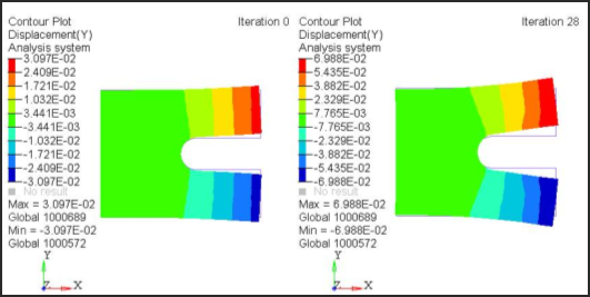
3 ) When I plot the displacement, I see the same shape in Iteration 0 and in Iteration 28 (the final one). Can I see the displacement of the optimized shape directily or Have I to produce a new geometry and create a new model?
Thank you very much.
Answers
-
HI,
1) Element density>> Element volume
2)& 3) You can define the Entry 'DENSITY, H3D, ALL' in your optimization input file (in HyperMesh through control cards - DENSITY. This will allow to plot the displacement or stress contour on the optimized isosurface in HyperView (density and displacements will be in one common result file).
0 -
With the density method, the material density of each element is directly used as the design variable and varies continuously between 0 and 1; these represent the state of void and solid, respectively. Intermediate values of density represent fictitious material. The stiffness of the material is assumed to be linearly dependent on the density. This material formulation is consistent with our understanding of common materials. For example, steel, which is denser than aluminium, is stronger than aluminium. Following this logic, the representation of fictitious material at intermediate densities does reflect engineering intuitions.
In general, the optimal solution of problems involves large gray areas of intermediate densities in the structural domain. Such solutions are not meaningful when we are looking for the topology of a given material, and not meaningful when considering the use of different materials within the design space. Therefore, techniques need to be introduced to penalize intermediate densities and to force the final design to be represented by densities of 0 or 1 for each element. The penalization technique used is the “power law representation of elasticity properties,” which can be expressed for any solid 3D or 2D element as follows:
K(r) =K* ρ^p
where K and K represent the penalized and the real stiffness matrix of an element, respectively, ρ is the density and p the penalization factor which is always greater than 1.
In OptiStruct, the DISCRETE parameter corresponds to (p - 1). DISCRETE can be defined on the DOPTPRM bulk data entry. P usually takes a value between 2.0 and 4.0. For example, compared to the non-penalized formulation (which is equivalent to p=1) at ρ=0.3, p=2 reduces the stiffness of the element from 0.3 to 0.09 times the stiffness of the fully dense element. The default DISCRETE is 1.0 for shell dominant structures, and 2.0 for solids dominant structures (the dominance is defined by the proportion of number of elements). An additional parameter, DISCRT1D, can also be defined on the
500