Hello!
We have the following problem by using OSSmooth for a FEA reanalysis:
Our component is made up of a core (blue) and a shell (red/orange). The core has Hex 8 3D-Elements with the Card Image MAT 1 and PSolid. In order to create a shell around the core of the component, we used the tool 'Find Faces'. Thus we got a shell around the core with Quad 4 2D-Elements. We used the Card Image MAT8 and PShell with an offset to the outside T=2mm. Therefore there should be no intersection between the two kinds of elements (see figure 1). Both the core and the shell was defined as design space so that we optimized them both in a successful optimization. See figure 2: Holes and notches were created in the shell as well as in the core.
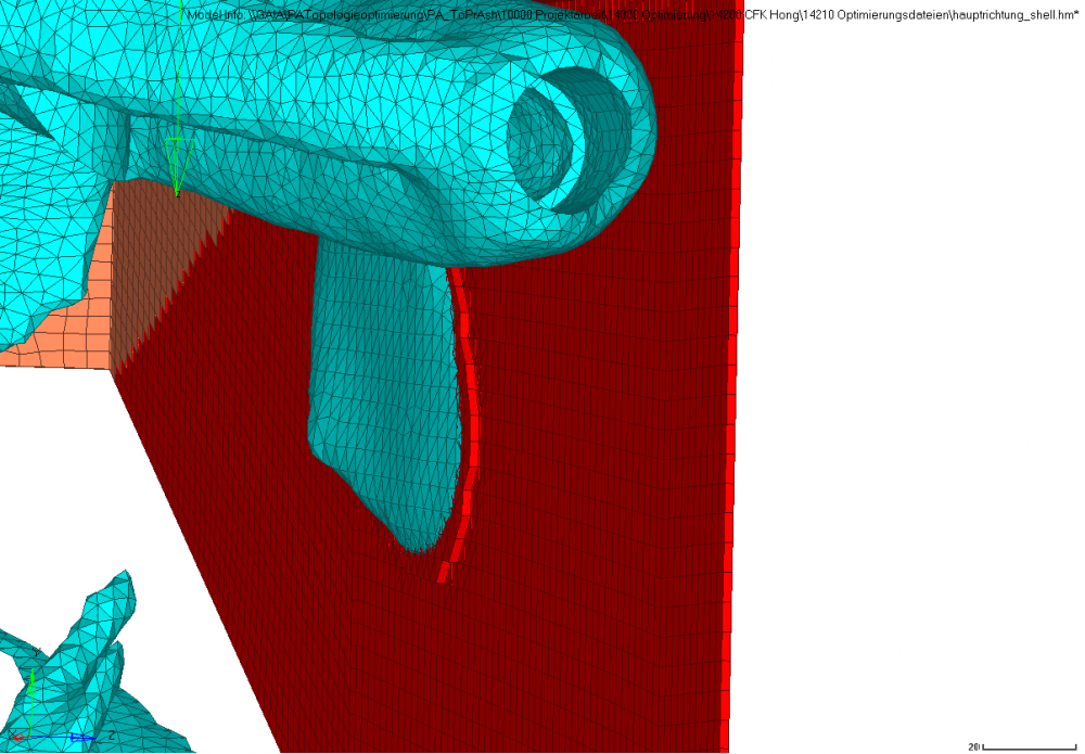
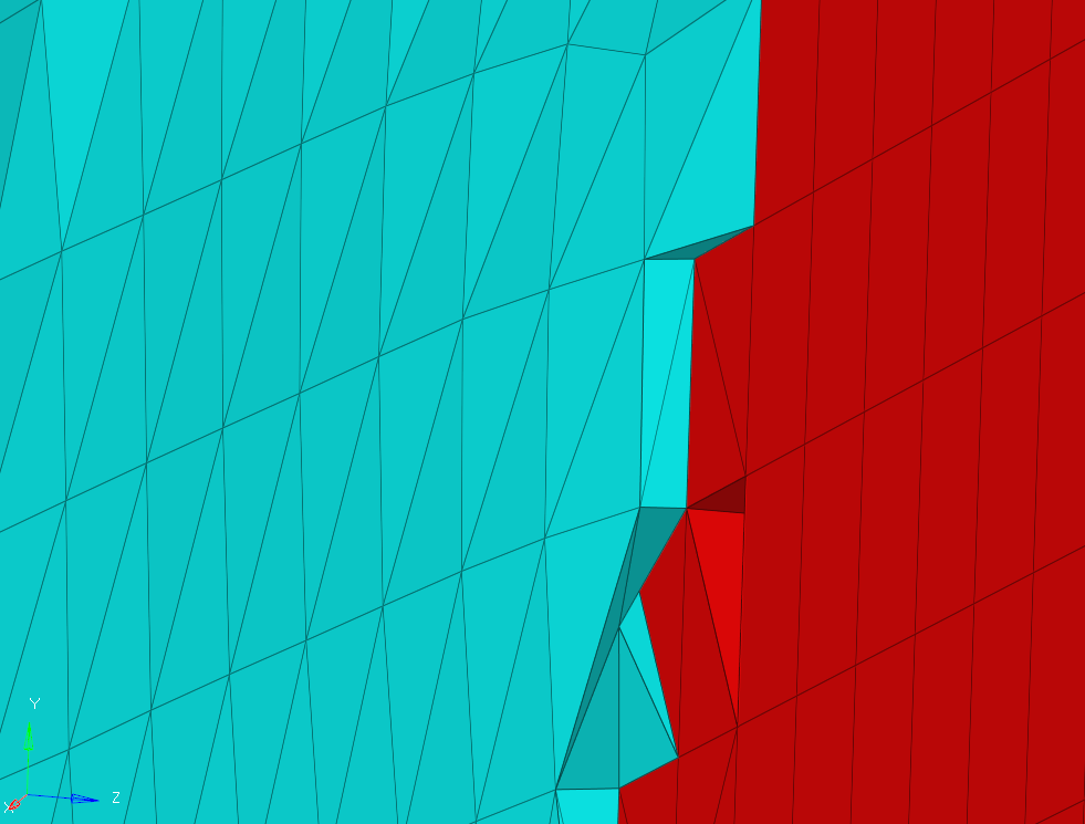
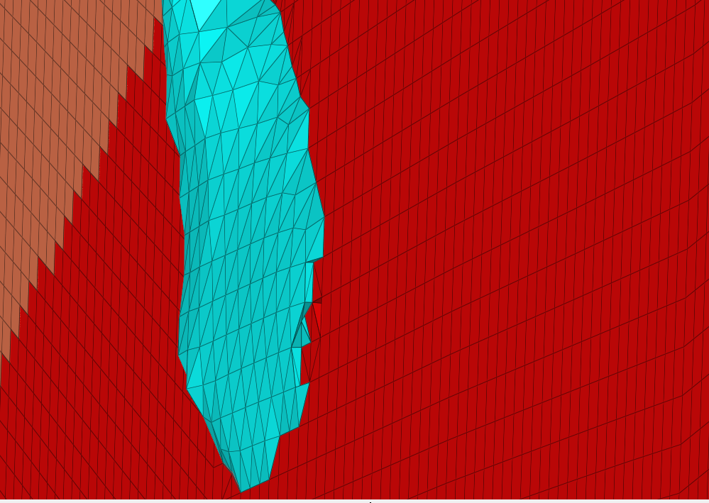
Afterwards, we tried to import the optimized geometry with OSSmotth by using the following settings: FEA Reanalysis, iso surface, remesh, trias as mesh type and two layers attached. As a result the 3D-Elements has been updated according to the optimization result, but not the shell (see figure 3). Furthermore we got a very questionably visualization of the shell elements: At the attachment points between core and shell, the shell elements strangely stick to the outside and inside (see figure 4 and 5).
Are there any mistakes in our settings or in the modelling?
Thank you very much in advance for your tips and advices!
Greetings
Martin
<?xml version="1.0" encoding="UTF-8"?>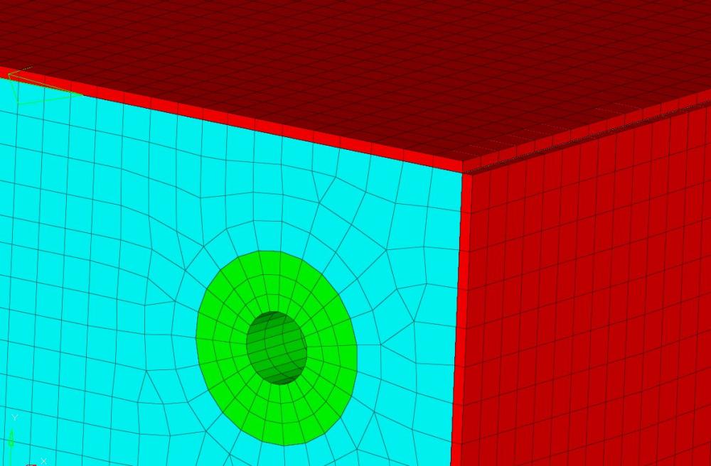
<?xml version="1.0" encoding="UTF-8"?>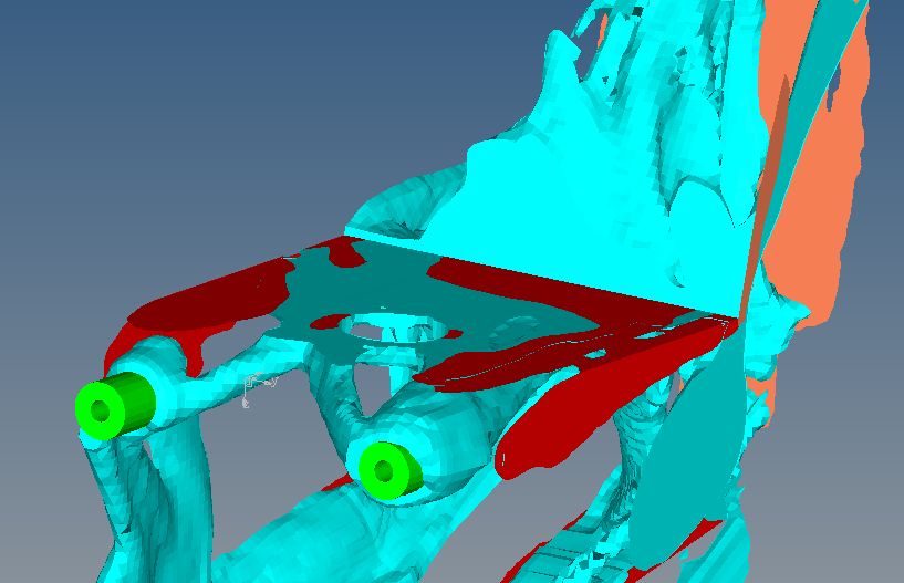
<?xml version="1.0" encoding="UTF-8"?>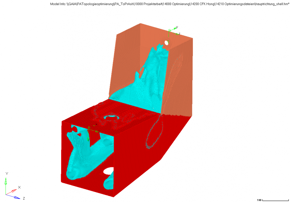
<?xml version="1.0" encoding="UTF-8"?>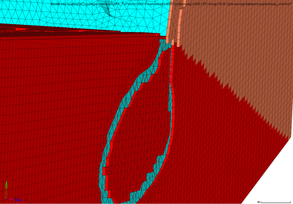
<?xml version="1.0" encoding="UTF-8"?>