In this post we discuss how to model a rotary dryer using Altair® EDEM™ coupled with Altair® AcuSolve™. Simulation files with an example already setup can be downloaded from here:
Rotary dryers are essential components in a wide range of industrial processes. Their robust and adaptable design makes them suitable for drying various materials, from agricultural products or biomass to minerals. In the example covered in this post the system of focus is an aggregate rotary dryer commonly used in asphalt manufacturing processes. The correct drying of the aggregates is key to achieving a high-quality asphalt, since the final quality highly depends on the moisture content of the aggregates. The main challenges faced when using rotary dryers are the following:
- Energy Consumption: Rotary Dryers can be significantly energy-intensive, so minor improvements on energy efficiency can lead to significant energy and cost savings.
- Equipment Wear: The exposure to abrasive materials and high temperatures can lead to significant wear reducing the lifespan of the equipment.
- Operational efficiency: Ensuring optimal performance to achieve the right moisture content on the aggregates at the end of the drying process by controlling precisely the temperature, airflow, and residence time.
Using EDEM, you can help resolve these challenges by modelling the dryer and using simulation to optimize its operation to achieve energy and operational efficiency improvements.

Step 1 - Set the material model
For this simulation a custom non-calibrated EDEM Material Model was created based on realistic values using the GEMM database as a starting point.
Material Models Libraries in EDEM
Since we are drying the particles and volume will be removed, additional volume that makes-up for the humidity/water content of the particles needs to be defined. This will be covered in step 4, however, in this step an additional “dummy” material needs to be created in EDEM. The material properties for it can be left with the default values.
Step 2 - Material Calibration
Materials should be calibrated or use existing material models:
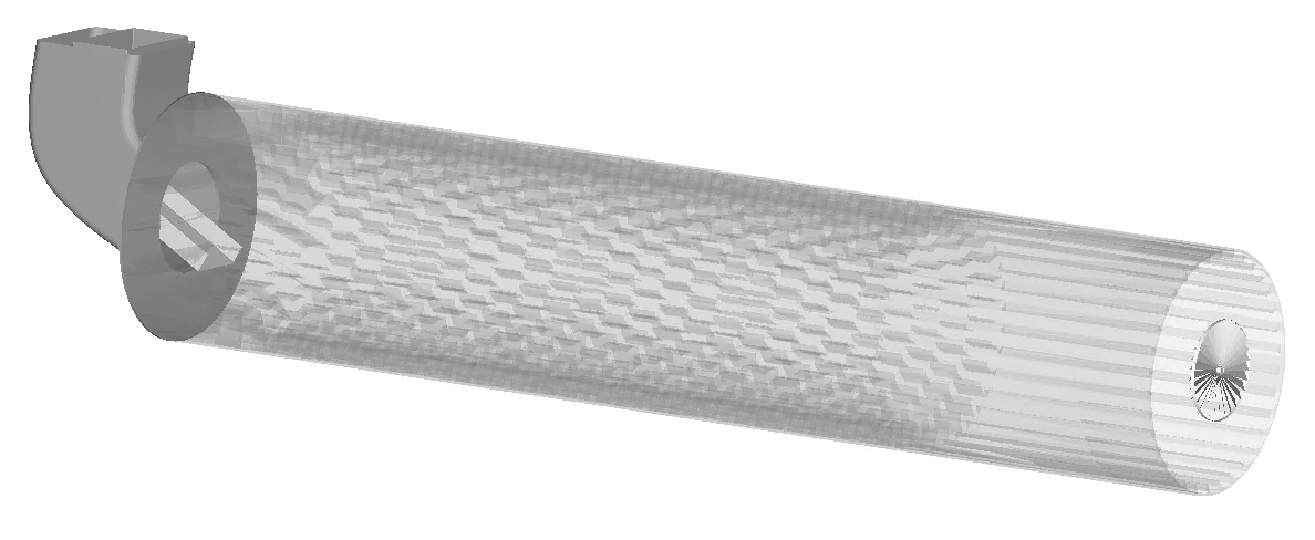
Step 3 - Import equipment from CAD
You can create your own equipment models in any CAD package and import it into EDEM, many file types such as STL, STEP, IGES to name a few, are supported. Geometries are imported to EDEM via the Creator > Geometries > Import Geometry section and will be meshed automatically unless the format imported already has a previously defined mesh. Generally, the mesh element size is not very important for DEM simulation results; however, you may want to manually modify the mesh size if you want to do some wear analysis on the dryer flights, as this an give a more detailed wear pattern.
Step 4 – Assign Kinematics, Set-up Physics & Define Factory
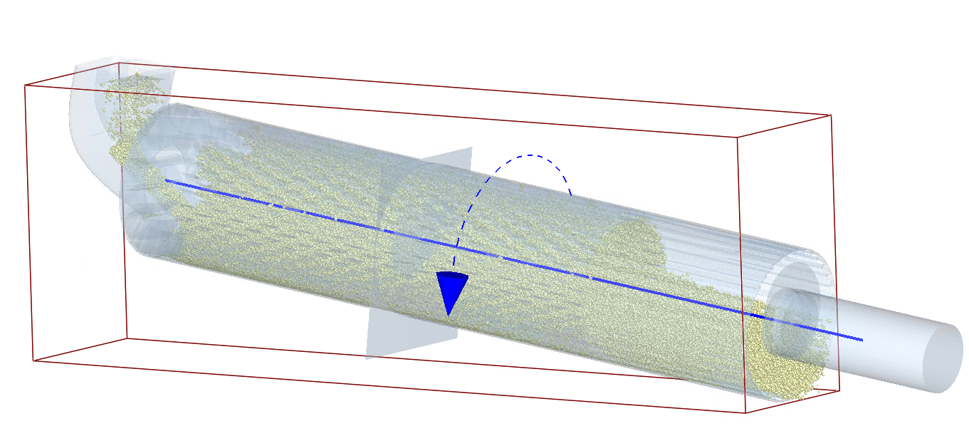
Different types of motion can be assigned to the geometries, but in a rotary dryer like the one in this example only one kinematic would be required. This would be a Linear Rotational Kinematic which rotates around a specified axis. The axis of rotation should be defined following the inclination of the dryer and through the main drum as shown in the image below. Make sure that the rotation direction is the correct one based on the arrangement of the flights.
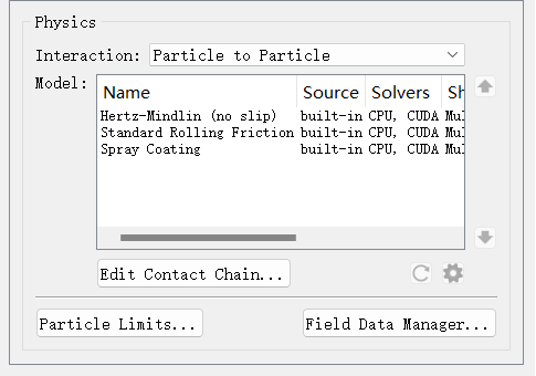
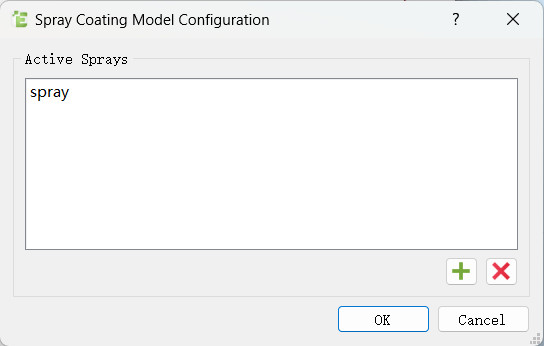
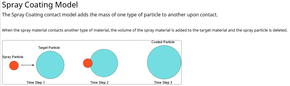
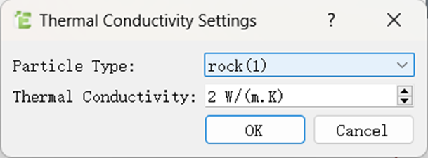
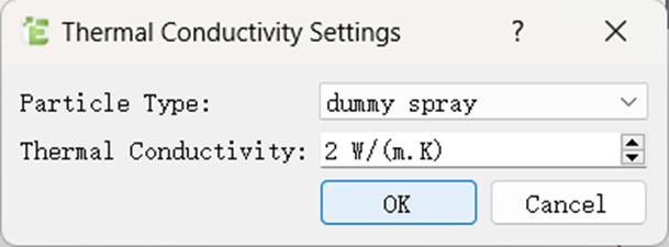
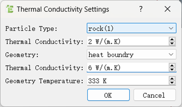
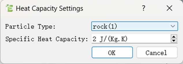
In the Physics section, for Particle-Particle interactions, add the Heat Conduction and The Spray Coating additional models. With Heat Conduction selected, click on the settings wheel and define the material’s thermal conductivity. Do the same with the Spray Coating and add the “dummy spray” material created earlier as the spray. Then in the Particle Body Force interaction, add the Temperature Update. Select Temperature Update and click on the model settings wheel to define the Specific Heat Capacity for the material.
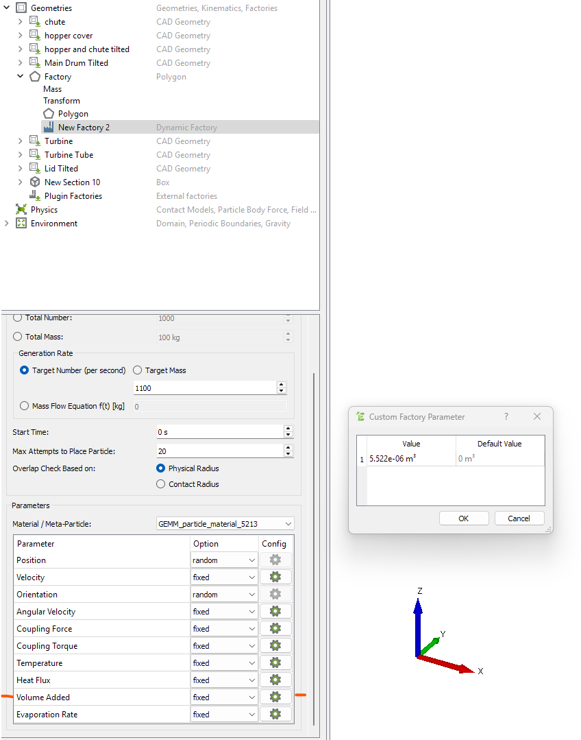
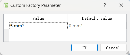
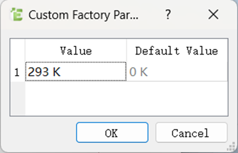
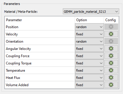
Create and define a factory to generate the material that needs drying in the chute/hopper area before the start of the dryer. In the factory parameters set the starting temperature and the Volume added (volume of water compared to a fully dry particle).
Step 5 – Set-up the AcuSolve model
Tutorials and guides on setting up EDEM - AcuSolve coupled simulations can be found here: EDEM-AcuSolve Tutorials, the other sections in the page will cover other aspects of AcuSolve modeling, including introductory tutorials.
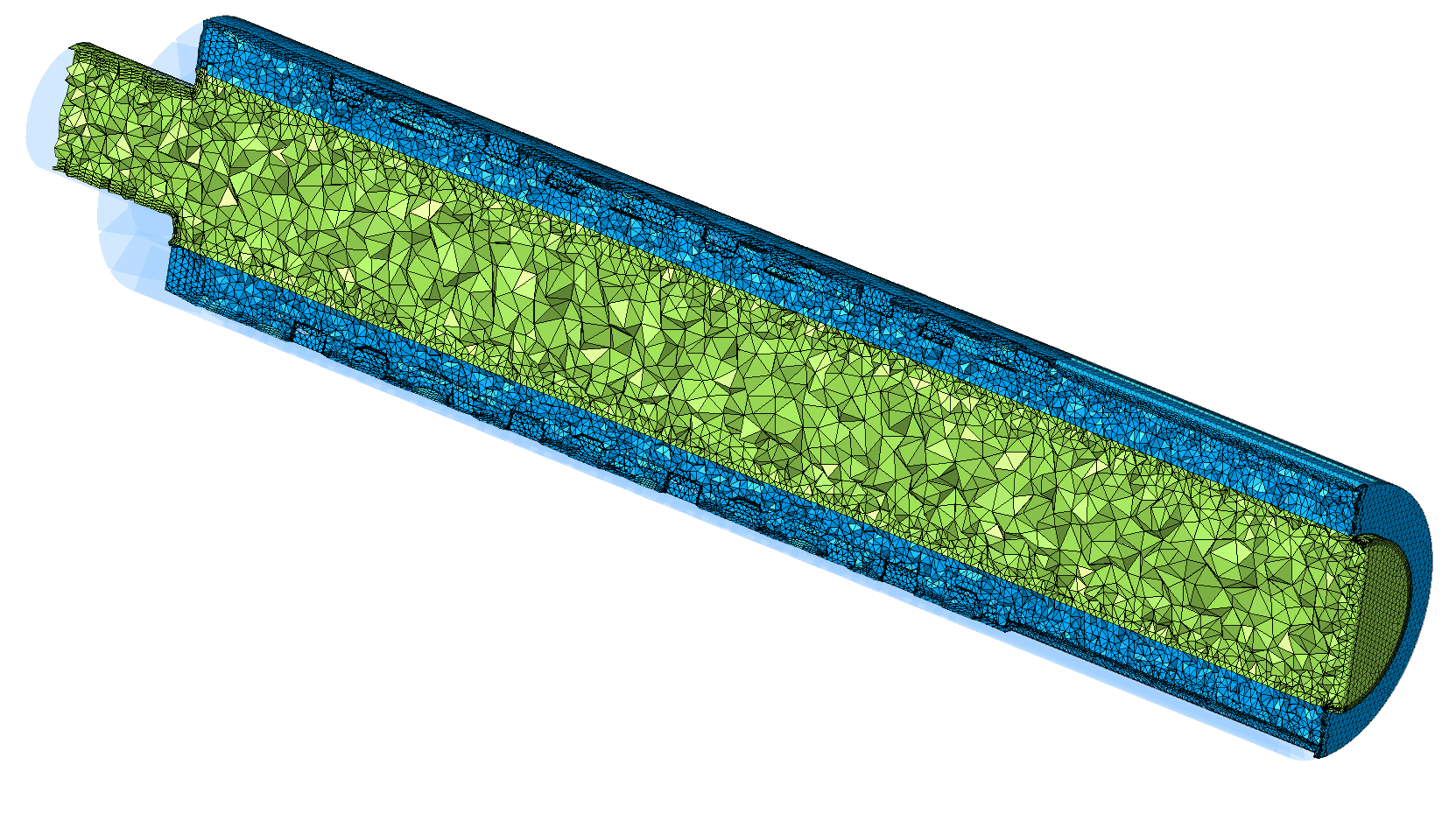
In Simlab, import the dryer CAD files and extract the Fluid domain. Split the fluid domain in rotating and non-rotating zones.
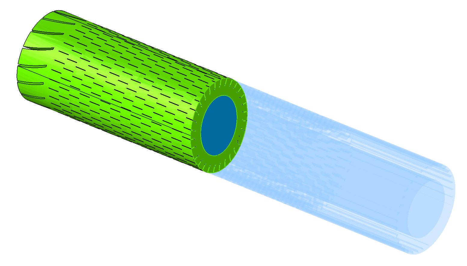
Rotating mesh motion (sliding mesh technique) will be utilized to resolve the rotation of the blades/drum. After the definition of the fluid domain proceed with meshing of both volumes. Historically, CFD-DEM codes had a major limitation when it came to the particle to CFD mesh size ratio. The users were forced to use CFD meshes with element sizes 3-5 times larger than the particle size. AcuSolve, however, uses a geometric interpolation and diffusion method for calculating the particle solid volume fraction, which allows the mesh size to be smaller than the particle size if needed.
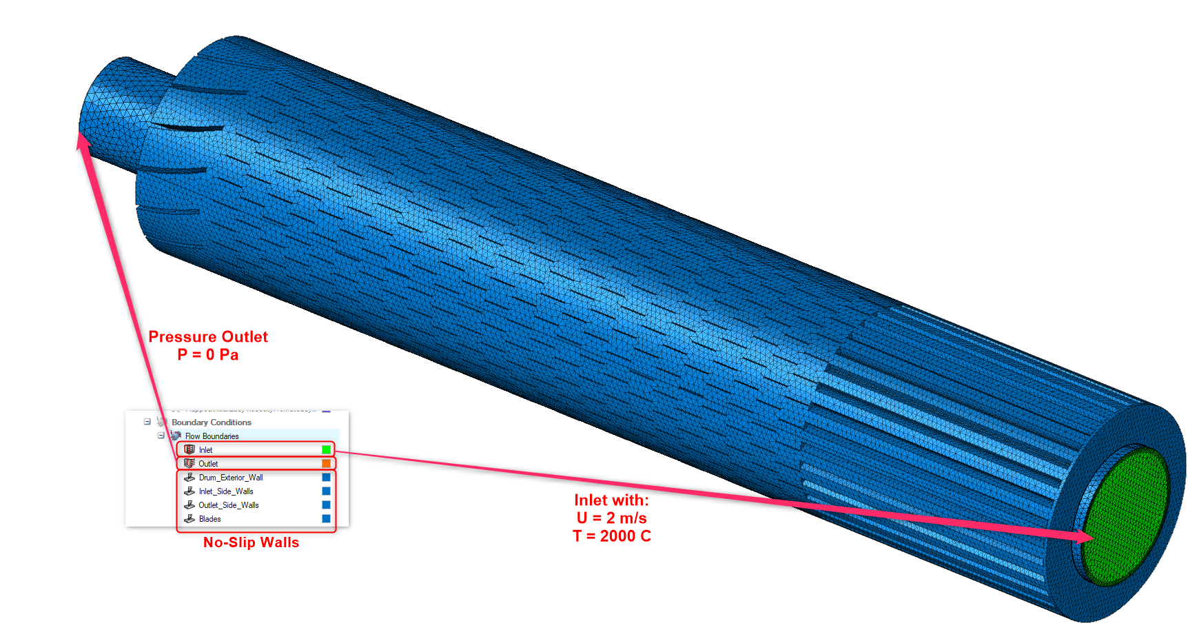
After creating the mesh define a “Flow” solution and assign the desired flow boundary conditions
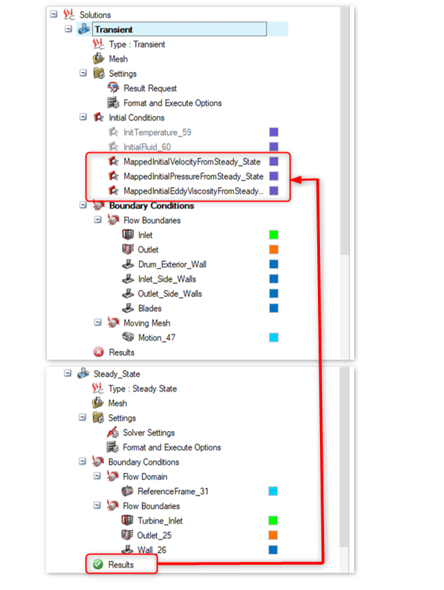
A transient AcuSolve simulation will be employed for the AcuSolve-EDEM two-phase simulation. However, it is a common practice to first run a steady-state Acusolve-alone simulation and use its results (pressure, velocity, etc) as initial conditions for the transient simulation.
Step 6 – Run the coupled simulation
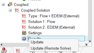
Make sure that the coupling server is open in EDEM by clicking this button in the toolbar:

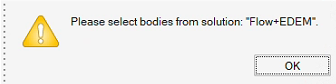
Define your EDEM timestep, save interval, selective save (optional) and solver Engine. Then from Simlab launch the AcuSolve coupled solution solve. For this, right click on Results and then click on Update.
Step 7 – Post-Processing
Altair EDEM allows engineers to analyze the rotary dryer operation to:
- Maximize energy efficiency by predicting the drying rate of the material and other detrimental phenomena in the process
- Optimize the rotational speed and other operational parameters to maximize efficiency
- Predict the impact of different flights shapes and sizes on the drying process
- Obtain key insight into the drying conditions of different bulk materials at different starting moisture content levels
- Predict maintenance requirements and wear on the system
- Get an insight into the system at real scale


If you are interested in other examples coupling EDEM and AcuSolve check these other articles: